
A transmission rod joint

A transmission rod and transmission shaft technology, applied in the field of transmission rod joints, can solve the problems of weakening the flexibility and adaptability of mechanical equipment, the limitation of mechanical work fields, and the inability to increase or decrease the length of transmission rods, etc., so as to achieve easy processing, manufacturing and disassembly Effects of maintenance, increased flexibility and adaptability, good assembly interchangeability

Active Publication Date: 2017-04-05
GUANGXI UNIV
View PDF10 Cites 0 Cited by
  • Summary
  • Abstract
  • Description
  • Claims
  • Application Information

AI Technical Summary

Problems solved by technology

However, there is a common problem in engineering applications that use lengthened transmission rods to achieve long-distance power transmission: when mechanical equipment similar to long-handled garden pruners become commodities and are provided to users, their working length It is determined that the length of the transmission rod cannot be increased or decreased according to the actual work needs, so that the mechanical work field is limited, which weakens the flexibility and adaptability of the mechanical equipment work
The reason is that there is currently no simpler and more practical connecting joint that can easily connect the drive rods joint by joint

Method used


Image

  • A transmission rod joint
  • A transmission rod joint

Examples


Embodiment 1

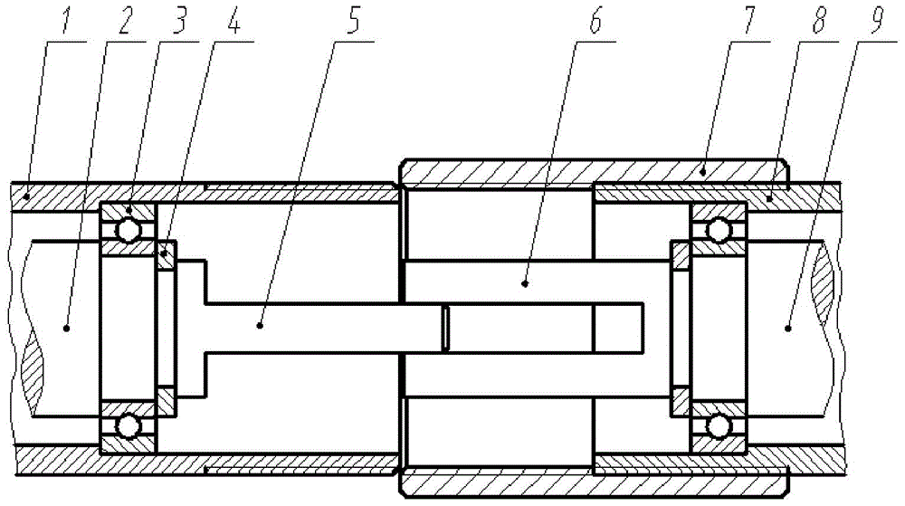
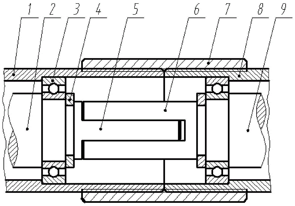
[0024] Such as Figure 1-2 As shown, a transmission rod joint is mainly composed of a convex shaft head 5 integrally manufactured with the end of the transmission shaft A2, a concave shaft head 6 and a connecting sleeve 7 integrally manufactured with the end of the transmission shaft B9; Type shaft head 5 fits with concave type shaft head 6; said connecting sleeve 7 is provided with internal thread; the outer surface of hollow tube A1 end and hollow tube B8 end are respectively provided with external thread; said connecting sleeve Both ends of the barrel 7 are threadedly connected with the hollow pipe A1 and the hollow pipe B8 respectively. The convex shaft head 5 and the concave shaft head 6 are connected to form a slot-shaped concave-convex connection structure. The length of the external thread at the end of the hollow pipe A1 and the end of the hollow pipe B8 is half of the length of the connecting sleeve 7 . When the connecting sleeve 7 was screwed into the end of the e...

Embodiment 2

[0026] The difference between this embodiment and Embodiment 1 is that: the convex shaft head 5 and the end of the transmission shaft A2 are fixed together by welding; the concave shaft head 6 and the end of the transmission shaft B9 are fixed together by welding .

Embodiment 3

[0028] The difference between the present embodiment and the first embodiment is only that: the convex shaft head 5 and the concave shaft head 6 are connected to form a cross-groove concave-convex connection structure.


PUM


Abstract

The invention discloses a transmission rod joint. The transmission rod joint mainly comprises a convex spindle head (5), a concave spindle head (6) and a connecting sleeve (7), wherein the convex spindle head (5) is arranged at an end of a transmission shaft A (2); the concave spindle head (6) is arranged at an end of a transmission shaft B (9); the convex spindle head (5) is matched with the concave spindle head (6); inner threads are arranged in the connecting sleeve (7); outer threads are respectively arranged on an outer surface of an end of a hollow tube A (1) and an outer surface of an end of a hollow tube B (8); and two ends of the connecting sleeve (7) are respectively in threaded connection with the hollow tube A (1) and the hollow tube B (8). The transmission rod joint is simple in structure, high in universality, convenient to assemble and disassemble and easy to operate. By the transmission rod joint, the number of sections of a transmission rod can be increased or decreased at any time as needed, so that the length of the transmission rod can be increased or reduced, and the flexibility and the adaptability on remote power transmission of mechanical equipment are improved.

Description

technical field [0001] The invention belongs to the auxiliary equipment of the transmission structure, and in particular relates to a transmission rod joint used for connecting two transmission rods. Background technique [0002] In mechanical engineering, power is often transmitted over long distances by means of gear trains, belts, chains, drive shafts, etc. Among them, transmission shaft transmission is a transmission method with unique advantages. The drive shaft transmission has the characteristics of simple structure, good rigidity, strong maneuverability, high mechanical efficiency, good adaptability and reliability, etc., and can conveniently realize large-span power transmission. In engineering applications, the transmission shaft can be separated from the fixed base support and installed in the hollow pipe wall through bearings to make a movable hand-held transmission rod. The long-handled chainsaw that the garden department uses at present utilizes the transmiss...

Claims


Application Information

Patent Timeline
Patent Type & Authority Patents(China)
IPC IPC(8): F16D1/00
Inventor 刁海林蔡道雄唐继新
Owner GUANGXI UNIV
Learn More