Crack detection device for columnar parts

A technology for crack detection and parts, which is applied in the field of crack detection devices for columnar parts, can solve problems such as low work efficiency, scanning loophole areas, and uncertain scanning ranges, so as to ensure scanning quality, improve work efficiency, and reduce manual operations Effect

Active Publication Date: 2019-10-08
无锡锡西模锻有限公司
View PDF5 Cites 4 Cited by
  • Summary
  • Abstract
  • Description
  • Claims
  • Application Information

AI Technical Summary

Problems solved by technology

[0002] Part surface gap detection is an important inspection process before parts leave the factory. With the development of science and technology and the improvement of industrial automation level, industrial production has higher and higher requirements for parts defects. Traditional part crack detection mainly relies on manual use of hand-held equipment. The scanning range is uncertain, and there are prone to scanning loopholes, which makes the scanning results inaccurate. At the same time, the handheld device can only scan the part in one direction. When scanning in multiple directions, the part needs to be turned manually, which is time-consuming and laborious, and the work efficiency is low.

Method used


Image

  • Crack detection device for columnar parts
  • Crack detection device for columnar parts
  • Crack detection device for columnar parts

Examples


Embodiment Construction

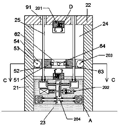
[0020] Combine below Figure 1-Figure 6 The present invention is described in detail, and for convenience of description, the orientations mentioned below are now stipulated as follows: figure 1 The up, down, left, right, front and back directions of the projection relationship itself are the same.

[0021] The present invention relates to a crack detection device for cylindrical parts, which is mainly used in the process of part detection. The present invention will be further described below in conjunction with the accompanying drawings of the present invention:

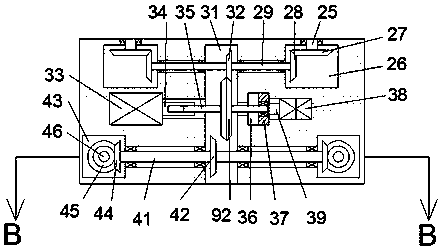
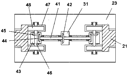
[0022] A crack detection device for column parts according to the present invention comprises two uprights 21, the upper ends of the two uprights uprights 21 are fixedly connected with crossbeams 22, and the crossbeams 22 are provided with two through holes 91, so A detection chamber 24 is provided between the crossbeam 22 and the column 21, the front and rear ends of the detection chamber 24 are connected to the ...


PUM


Abstract

The invention discloses a crack detection device for columnar parts. The crack detection device comprises two stand columns; a cross beam is fixedly connected to the upper ends of the two stand columns, two through holes are formed in the cross beam, a detection cavity is formed between the cross beam and the stand columns, the front end and the rear end of the detection cavity communicate with the outside, a lifting block is arranged in the detection cavity in a sliding mode, and an automatic fastening device is arranged on the lower end surface of the cross beam and the upper end face of thelifting block. Due to the fact that a lifting type automatic clamping device is adopted, the parts can be directly and completely scanned after being fixed, meanwhile, a self-rotation lifting type scanning structure is adopted to carry out system scanning on a to-be-detected part, so that the scanning quality and the scanning speed are guaranteed, the initial position is automatically returned after scanning is completed, the actions of the device are all automatically carried out, so that the manual operation is reduced, and the working efficiency is improved.

Description

technical field [0001] The technical field of component detection of the present invention is specifically a crack detection device for columnar components. Background technique [0002] Part surface gap detection is an important inspection process before parts leave the factory. With the development of science and technology and the improvement of industrial automation level, industrial production has higher and higher requirements for parts defects. Traditional part crack detection mainly relies on manual use of hand-held equipment. The scanning range is uncertain, and there are prone to scanning loopholes, making the scanning results inaccurate. At the same time, the handheld device can only scan the part in one direction. When scanning in multiple directions, the part needs to be turned manually, which is time-consuming and laborious, and the work efficiency is low. Contents of the invention [0003] technical problem: [0004] Traditional hand-held scanning equipment...

Claims


Application Information

Patent Timeline
Patent Type & Authority Applications(China)
IPC IPC(8): G01M13/00
CPCG01M13/00B65G47/905G01M99/00
Inventor 朱晓凤
Owner 无锡锡西模锻有限公司
Why Eureka
Try Eureka