Sloping roof building rainwater drainage device

A technology for drainage devices and sloping roofs, which can be used in the direction of roof drainage, roofs, buildings, etc., and can solve problems that affect drainage.

Inactive Publication Date: 2019-10-15
SINO RISING SUN CONSTR GRP
View PDF7 Cites 5 Cited by
  • Summary
  • Abstract
  • Description
  • Claims
  • Application Information

AI Technical Summary

Problems solved by technology

However, due to the low height of this kind of building, more debris such as leaves will accumulate on the roof. This debris will flow into the water inlet of the siphon drainage pipe with the rainwater. If it is not treated in tim

Method used


Image

  • Sloping roof building rainwater drainage device
  • Sloping roof building rainwater drainage device

Examples


Embodiment Construction

[0017] The following will clearly and completely describe the technical solutions in the embodiments of the present invention with reference to the accompanying drawings in the embodiments of the present invention. Obviously, the described embodiments are only some, not all, embodiments of the present invention. Based on the embodiments of the present invention, all other embodiments obtained by persons of ordinary skill in the art without making creative efforts belong to the protection scope of the present invention.

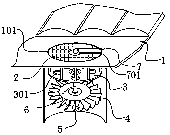
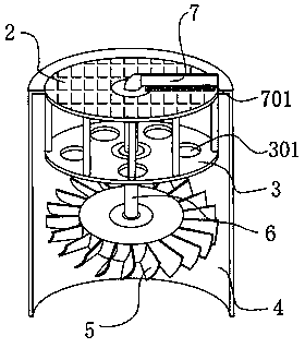
[0018] see Figure 1-2 , the present invention provides a technical solution: a rainwater drainage device for a building with a sloping roof, comprising a sloping roof 1, the bottom of the sloping roof 1 is provided with a drainage groove 101, and a grid plate 2 is movable installed in the drainage groove 101. The lower end of the grid plate 2 is fixedly installed with the siphon plate 3 through the connecting rod. The siphon plate 3 is installed on the upper ...


PUM


Abstract

The invention discloses a sloping roof building rainwater drainage device. The device comprises a sloping roof. A drainage groove is formed in the bottom end of the sloping roof in a penetrating mode.A grating plate is movably mounted in the drainage groove. A siphon plate is fixedly mounted at the lower end of the grating plate through connecting rods and mounted at the upper end of a drainage pipe. A turbine is rotationally arranged in the drainage pipe. The upper end of the turbine is fixedly connected with a rotary shaft. The rotary shaft movably penetrates through the middle of the siphon plate through a bearing, and in addition, the top end of the rotary shaft movably penetrates through the grating plate. The top end of the rotary shaft is located outside the grating plate and transversely and fixedly connected with a scraping plate. A bristlebrush is arranged at the bottom end of the scraping plate and makes movable contact with the top surface of the grating plate. When a water inlet of the drainage pipe is blocked, only a worker dredging method is available in the prior art. Through the rainwater drainage device provided by the invention, the turbine can be driven to rotate under the effect of rainwater flow, accordingly, the scraping plate provided with the bristlebrush is made to rotate repeatedly on the top surface of the grating plate, and tree leaves are scrapedoff the surface of the drainage pipe.

Description

technical field [0001] The invention relates to the technical field of rainwater drainage for buildings, in particular to a rainwater drainage device for buildings with sloped roofs. Background technique [0002] In the field of roof drainage of buildings with sloped roofs, siphon drainage pipes are usually used to drain the roof. However, due to the low height of this kind of building, more debris such as leaves will accumulate on the roof. This debris will flow into the water inlet of the siphon drainage pipe with the rainwater. If it is not treated in time, the debris such as leaves will easily accumulate. At the water inlet of the drainpipe, the drainage is affected. For this reason, we propose a rainwater drainage device for buildings with sloped roofs to solve the above problems. Contents of the invention [0003] The object of the present invention is to provide a rainwater drainage device for buildings with sloped roofs, so as to solve the problems raised in the a...

Claims


Application Information

Patent Timeline
IPC IPC(8): E04D13/04E04D13/064
CPCE04D13/0404E04D13/064E04D13/08
Inventor 张旭东
Owner SINO RISING SUN CONSTR GRP
Why Eureka
Try Eureka