Embedded floor lamp

A floor lamp, embedded technology, applied in lighting devices, light sources, fixed lighting devices, etc., can solve the problems of inconvenient adjustment of height and rotation angle of floor lamps, the impact of customers' daily use needs, and the height of floor lamps.

Pending Publication Date: 2019-10-18
广东华悦美照明科技有限公司
View PDF0 Cites 5 Cited by
  • Summary
  • Abstract
  • Description
  • Claims
  • Application Information

AI Technical Summary

Problems solved by technology

In some modern minimalist home designs that are popular now, the fashionable and unique shape and convenient use make the public more and more popular. The use of this kind of lamps is quite common. There are many types of floor lamps on the market, but the general floor lamps are more Tall, most of them are directly fixed on the ground, which takes up more space in the room and is not convenient for storage and use. Moreover, ordinary floor lamps are not easy to adjust the height and rotation angle, which affects the daily use needs of customers.

Method used


Image

  • Embedded floor lamp
  • Embedded floor lamp
  • Embedded floor lamp

Examples


Embodiment 1

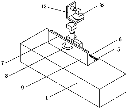
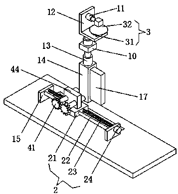
[0021] An embedded floor lamp, comprising a housing 1, a bracket 15, a connecting rod 14, a connecting plate 10 and a fixing frame 12; The top cover 9 is hinged on the surface at the left edge of the through groove 5; the casing 1 is embedded in the floor, and the device can be stored in the inner cavity as a whole, saving space; the number of brackets 15 is two, and the two brackets 15 are respectively set On the left and right sides of the bottom of the through groove 5, two supports 15 are provided with a reciprocating mechanism 2, and the upper surface of the reciprocating mechanism 2 is provided with a rotating mechanism 4; connecting rod 14 is fixedly connected to the right side of rotating mechanism 4, and connecting rod 14 The top of the top is provided with an electric lifting rod 13; the height can be adjusted by the electric lifting rod 13; the connecting plate 10 is placed on the lifting end of the electric lifting rod 13, and the upper surface of the connecting pla...

Embodiment 2

[0025] The difference between this embodiment and Embodiment 1 is:

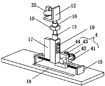
[0026] In this embodiment, the lamp 3 includes an LED lamp bead 31 and a lamp holder 32, the lamp holder 32 is placed at the telescopic end of the electric telescopic rod 11, the bottom array of the lamp holder 32 is provided with the LED lamp bead 31, and the input end of the LED lamp bead 31 It is electrically connected with the output terminal of the control switch group 19.

[0027] It also includes a support block 17 and a support groove 18, the support block 17 is placed on the front side of the connecting rod 14, and the support groove 18 is placed at the bottom of the through groove 5 and adapted to the support block 17.

[0028] Specifically, it is set in this way that the brightness can be adjusted by controlling the number of LED lamp beads 31 lit by the control switch group 19. When the device is retracted into the housing 1, the support block 17 snaps into the support groove 18 to play a supporti...

Embodiment 3

[0030] The difference between this embodiment and Embodiment 1 is:

[0031] In this embodiment, it also includes a card slot 6 and a card bar 7 , the card bar 7 is placed on the upper edge of the right side of the top cover 9 , and the card slot 6 is placed on the bottom edge of the through groove ( 5 ) and fits with the card bar 7 .

[0032] It also includes an elastic handle 8, which is placed on the left side of the top cover 9.

[0033] Specifically, with such arrangement, the top cover 9 and the housing 1 can be fixed and locked by the clamping strip 7 and the clamping slot 6 , and the top cover 9 can be opened and closed by the elastic handle 8 .

[0034] When using:

[0035]Embed the shell 1 into the floor so that the upper surface of the shell 1 is flush with the floor. When in use, turn on the power and control the lifting of the electric lifting rod 13 through the control switch group 19 to adjust the height of the lamp 3. By controlling the switch group 19 control...


PUM


Abstract

The invention discloses an embedded floor lamp. The embedded floor lamp comprises a shell, two supports, a connecting rod, a connecting plate and a fixed frame; the inside of the shell is hollow; a through groove is formed in the upper surface of the shell; the through groove is matched with the connecting rod, the connecting plate and the fixed frame; a top cover is hinged to the position, located on the left side edge of the through groove, of the upper surface of the shell; the two supports are arranged on the left side and the right side of the bottom of the through groove respectively; reciprocating mechanisms are arranged on the two supports; and rotating mechanisms are arranged on the upper surfaces of the reciprocating mechanisms. The embedded floor lamp can be folded for storage,and a height and a rotation angle can be conveniently adjusted during use, so that the daily use requirements of customers can be better met; the folding storage of the lamp can be realized through the rotating mechanisms and electric telescopic rods; and through electric lifting rods, third motors and the reciprocating mechanisms, the height adjustment, the angle rotation and the horizontal position movement of the lamp can be realized.

Description

technical field [0001] The invention relates to the technical field of lamps, in particular to an embedded floor lamp. Background technique [0002] Floor lamps: usually divided into up-illuminated floor lamps and direct-illuminated floor lamps, generally arranged in living rooms and rest areas, used in conjunction with sofas and coffee tables to meet the needs of local lighting in the room and decoration of the home environment. In some modern minimalist home designs that are popular now, the fashionable and unique shape and convenient use make the public more and more popular. The use of this kind of lamps is quite common. There are many types of floor lamps on the market, but the general floor lamps are more Tall, most of them are directly fixed on the ground, which takes up more space in the room and is not convenient for storage and use. Moreover, ordinary floor lamps are not easy to adjust the height and rotation angle, which affects the daily use needs of customers. ...

Claims


Application Information

Patent Timeline
Patent Type & Authority Applications(China)
IPC IPC(8): F21S8/02F21V21/15F21V21/22F21V21/30F21Y115/10
CPCF21S8/028F21V21/15F21V21/22F21V21/30F21Y2115/10
Inventor 李群李光杰
Owner 广东华悦美照明科技有限公司
Why Eureka
Try Eureka