

Triggering signal generation method for adjustable frequency divider
A technology of trigger signal and generation method, which is applied in the field of signal processing, can solve problems such as waveform display shaking, achieve the effect of intelligent trigger function and solve the problem of synchronous triggering
Active Publication Date: 2019-10-18
UNIV OF ELECTRONICS SCI & TECH OF CHINA
View PDF10 Cites 2 Cited by
- Summary
- Abstract
- Description
- Claims
- Application Information
AI Technical Summary
Problems solved by technology
The holdoff time setting is very useful for the stable display of FM / AM / PM signals, but if the trigger holdoff time is set incorrectly, the oscilloscope will still overlap signals with different "rising edges" as trigger points, resulting in waveform display shaking
Method used
View moreImage
Smart ImageViewing Examples

Examples
Embodiment
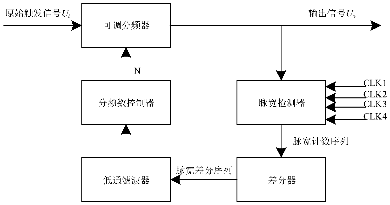
[0023] image 3 It is a flowchart of a method for generating a trigger signal of an adjustable frequency divider in the present invention.
[0024] In this embodiment, the initial frequency division number, sensitivity parameter and pulse width detector operating clock of the adjustable frequency divider are set;
[0025] Initialize the frequency division number N of the adjustable frequency divider as 1;
Login to View More PUM
 Abstract
The invention discloses a triggering signal generation method for an adjustable frequency divider. The method comprises the steps of performing frequency division on an input signal and then outputting, and then further measuring the pulse width of the output signal and periodically detecting the features of the output signal; then smoothly filtering a pulse width counting sequence, judging whether a filtered sequence value is more than a set threshold, and if the filtered sequence value is more than the set threshold, increasing the frequency division number of the adjustable frequency divider, and updating the output; and further performing measurement judgment until the filtered sequence value is less than the set threshold. Therefore, the quick automatic generation of the periodicallytriggered signal is achieved, so that the synchronous triggering problem of the complex signal is solved, the stable waveform of the complex signal can be automatically presented on the oscilloscope,and thus the triggering function of the oscilloscope is more intelligent.
Description
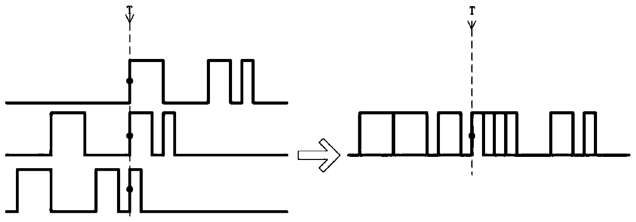
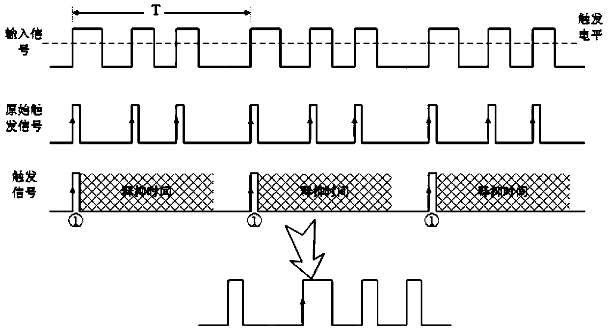
technical field [0001] The invention belongs to the technical field of signal processing, and more specifically relates to a method for generating a trigger signal of an adjustable frequency divider. Background technique [0002] As we all know, by setting specific trigger conditions, the oscilloscope can capture, store and stably display the measured signals that meet the conditions (characteristics). However, for complex signals, there may be multiple similar signal features in one cycle, which correspond to multiple trigger points, resulting in unstable waveform display. exist figure 1 In the left figure shown, the "rising edge" trigger condition is satisfied on the three rising edges of the input signal, therefore, in the figure 1 In the right graph shown, the waveform shows instability. To this end, the oscilloscope introduces the trigger holdoff function to solve this problem: after the oscilloscope triggers once, it will start the trigger holdoff time count, and th...
Claims
Login to View More Application Information
Patent Timeline
 Patent Type & AuthorityApplications(China)
IPC IPC(8): G01R13/02
CPCG01R13/0254
Inventor张沁川扈雅青黄武煌潘卉青邱渡裕叶芃
OwnerUNIV OF ELECTRONICS SCI & TECH OF CHINA