Outdoor electric control cabinet

A technology of electric control cabinet and cabinet body, applied in the field of electric control cabinet, can solve the problems of low efficiency and labor consumption, and achieve the effect of convenient use, increase service life, and meet the needs of use.

Inactive Publication Date: 2019-10-25
安徽蓝润正华电子有限公司
View PDF6 Cites 1 Cited by
  • Summary
  • Abstract
  • Description
  • Claims
  • Application Information

AI Technical Summary

Problems solved by technology

[0003] The purpose of the present invention is to solve the problem of labor-intensive and low efficiency in the prior art, and propose an outdoor electric control cabinet

Method used


Image

  • Outdoor electric control cabinet
  • Outdoor electric control cabinet
  • Outdoor electric control cabinet

Examples


Embodiment 1

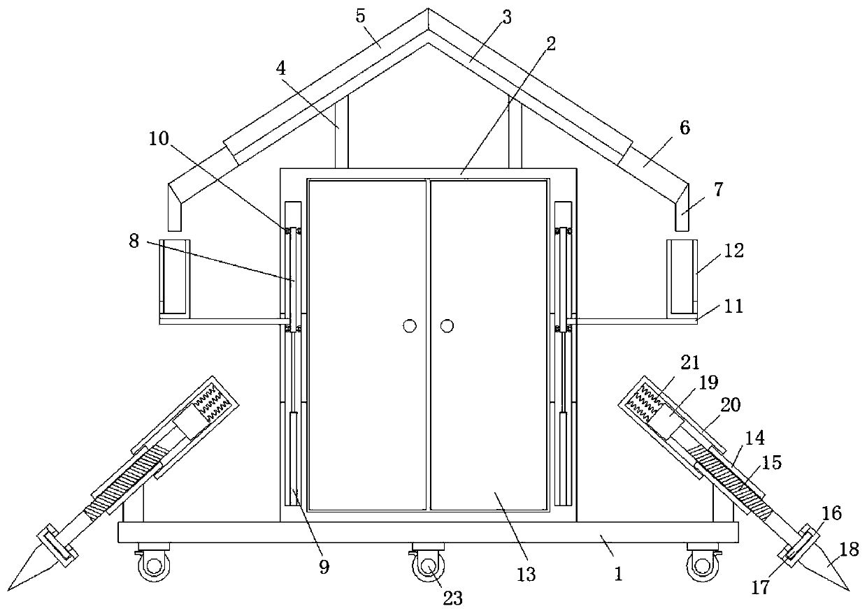
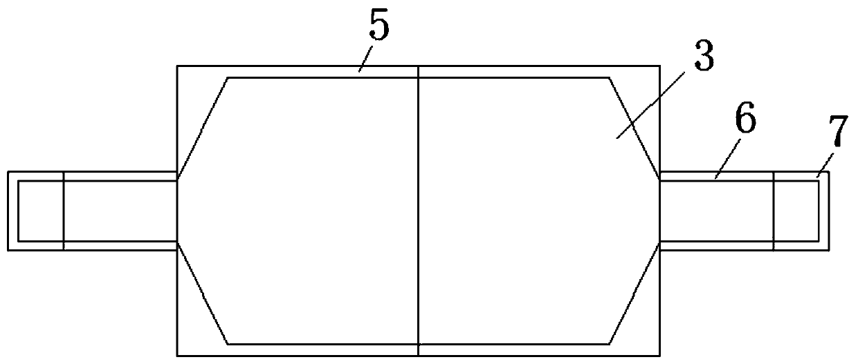
[0020] refer to Figure 1-3 , an outdoor electric control cabinet, including a bottom plate 1, a cabinet body 2 is fixedly welded on the top side of the bottom plate 1, and a pointed sloping plate 3 is arranged on the top side of the cabinet body 2, and between the pointed top sloping plate 3 and the top outside of the cabinet body 2 A support frame 4 is provided, and deflectors 5 are fixedly connected to the top side edge positions of the pointed sloping plate 3, and the sides of the deflectors 5 that are far away from each other are respectively folded and communicated with an oblique downpipe 6, and the oblique downpipe One end of 6 is communicated with vertical downpipe 7, and the two sides of cabinet body 2 are respectively provided with ventilating hole, and the mouth place of ventilating hole is provided with cavity, is provided with sliding baffle 8 in the cavity, and the bottom of sliding baffle 8 Both sides are respectively connected with elastic struts 9, and the fo...

Embodiment 2

[0023] Such as figure 1 As shown, this embodiment is basically the same as Embodiment 1. Preferably, one side of the cabinet body 2 is connected with a cabinet door 13 through a hinge, and a door lock is provided between the cabinet doors 13, and a handle is provided on one side of the cabinet door 13. .

Embodiment 3

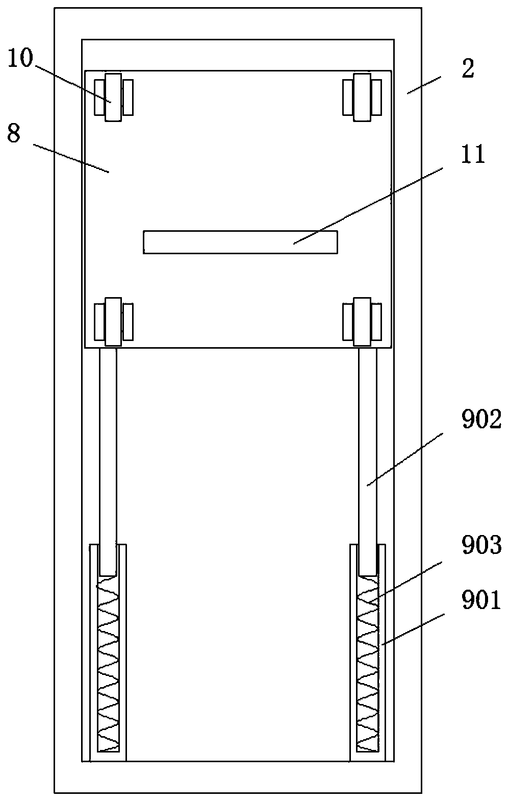
[0025] Such as figure 2 As shown, this embodiment is basically the same as Embodiment 1. Preferably, the elastic strut 9 includes a main rod 901, an auxiliary rod 902 and a spring set 1 903. The top end of the main rod 901 is fixedly connected to the bottom inner wall of the cavity, and the main rod 901 The top of the rod 901 is provided with a top groove, the bottom end of the auxiliary rod 902 is slidably connected in the top groove, the spring group one 903 is located between the bottom end of the auxiliary rod 902 and the inner wall of the bottom side of the top groove, and the top of the auxiliary rod 902 extends to The top side of the main rod 901 is fixedly connected with the bottom side of the sliding baffle 8 respectively.

[0026] In this embodiment, the spring group 1 903 in the elastic strut 9 plays a reset role, and can retract and contract under force when it rains, and can lift the sliding baffle 8 when it is not raining.


PUM


Abstract

The invention discloses an outdoor electric control cabinet. The cabinet comprises a bottom plate, and a cabinet body is fixedly welded to the top side of the bottom plate. A pinnacle inclined plate is arranged at the top side of the cabinet body, and a support frame is arranged between the pinnacle inclined plate and the outer side of the top of the cabinet body; flow guide plates are fixedly connected to the edges of the top side of the pinnacle inclined plate; the sides, away from each other, of the flow guide plates are folded and communicated with oblique drain pipes, and one end of eachoblique drain pipe is communicated with a vertical drain pipe; ventilation holes are formed at the two sides of the cabinet body correspondingly, and cavities are formed in edge openings of the ventilation holes; and sliding baffles are arranged in the cavities. The electric control cabinet is prevented from being invaded by rainwater in rainy days, thereby guaranteeing the normal operation of electrical elements in the electric control cabinet, and prolonging the service life of the electric control cabinet. Meanwhile, people can rapidly and stably install the electric control cabinet outdoors, thereby bringing convenience to people for the use, and meeting the use requirements of people in production and life.

Description

technical field [0001] The invention relates to the technical field of electric control cabinets, in particular to an outdoor electric control cabinet. Background technique [0002] The existing electric control cabinets often need to be installed outdoors during use, and the surrounding rings are also different. The electric control cabinets need to dissipate heat during use, and the traditional electric control cabinets are designed to prevent rainwater. Entering, the ventilation holes on both sides of the electric control cabinet will be opened smaller, and the temperature inside the electric control cabinet will be higher, resulting in a relatively high ambient temperature for the operation of electrical components in the electric control cabinet, resulting in failure of electrical components The rate is higher, and the service life is greatly shortened, and the larger cooling vent may be poured in by rainwater when the rain is heavy, causing greater losses, and during t...

Claims


Application Information

Patent Timeline
IPC IPC(8): H05K5/02
CPCH05K5/0213H05K5/0234
Inventor 庄连美陈万林秦喜春
Owner 安徽蓝润正华电子有限公司
Why Eureka
Try Eureka