Receiving antenna of optical communication system

A communication system and antenna technology, which is applied to antennas, folded antennas, antenna parts and other directions, can solve the problems of cumbersome and time-consuming, time-consuming and labor-intensive, and damaged conversion components, and achieves the effect of good fixation

Active Publication Date: 2021-05-28
广东中通通信科技有限公司
View PDF13 Cites 1 Cited by
  • Summary
  • Abstract
  • Description
  • Claims
  • Application Information

AI Technical Summary

Problems solved by technology

[0003] In the optical communication system, it is necessary to use the receiving antenna to receive the signal. However, the traditional receiving antenna is generally fixed on the pole directly by connecting the fixing parts such as bolts, but because the general receiving antenna is installed on the At high places, when fixing by bolts, professional installation tools are required to operate, and the bolts need to be screwed repeatedly. Generally, multiple bolts need to be screwed, which is time-consuming and laborious, and the installation is slow, which will pose a safety hazard. , it is also extremely inconvenient when it needs to be disassembled and repaired in the later stage, and the converter used to convert the receiving signal of the receiving antenna is generally installed at the same time as the receiving antenna. When installing separately, it is more cumbersome and time-consuming. There is no protective device on the cover, and the conversion components will be easily damaged by the harsh environment

Method used


Image

  • Receiving antenna of optical communication system
  • Receiving antenna of optical communication system
  • Receiving antenna of optical communication system

Examples


Embodiment Construction

[0027] In order to make the technical means, creative features, goals and effects achieved by the present invention easy to understand, the present invention will be further described below in conjunction with specific embodiments.

[0028] It should be noted that the terms "first" and "second" in the description and claims of the present application and the above drawings are used to distinguish similar objects, but not necessarily used to describe a specific sequence or sequence. It should be understood that the data so used may be interchanged under appropriate circumstances for the embodiments of the application described herein. Furthermore, the terms "comprising" and "having", as well as any variations thereof, are intended to cover a non-exclusive inclusion, for example, a process, method, system, product or device comprising a sequence of steps or elements is not necessarily limited to the expressly listed instead, may include other steps or elements not explicitly lis...


PUM


Abstract

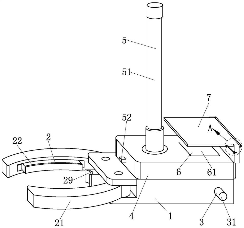
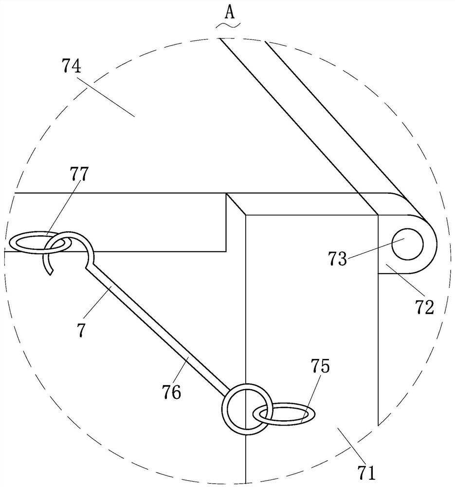
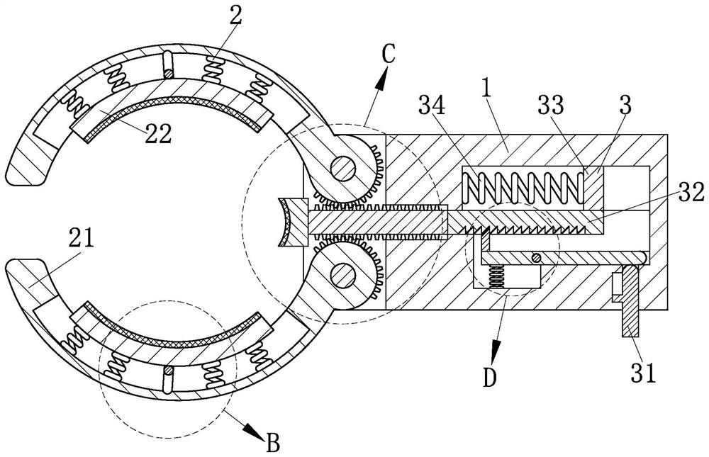
The invention relates to the field of signal receiving devices, and particularly discloses a receiving antennaof an optical communication system. The receiving antenna comprises a mounting base, a fixing structure, a limiting structure, a fixing base, a clamping structure, a locking structure and a protection structure. Through arrangement of the fixing structure, the antenna can be rapidly installed outside a circular electric pole through pressing force, electric poles with different diameters can be connected and fixed, fixation is firm, and through installation of the limiting structure in the installation base, the fixing structure can be automatically limited and fixed, the situation of slippage after the mounting base and the electric pole are mounted and fixed is prevented, limiting release of the fixing structure can be quickly realized through a labor-saving principle, the mounting base can be quickly dismounted and replaced, and the clamping structure is arranged in the fixing base, so that the antenna can be quickly and stably mounted and fixed; and therefore, the effects of saving time and labor and improving the mounting efficiency can be achieved.

Description

technical field [0001] The invention relates to a signal receiving device, in particular to a receiving antenna of an optical communication system, and belongs to the field of signal receiving devices. Background technique [0002] A signal is a physical quantity that represents a message. For example, an electrical signal can represent different messages through changes in amplitude, frequency, and phase. There are two types of electrical signals: analog and digital. A signal is a tool for carrying messages and a carrier of messages. In a broad sense, it includes optical signals, acoustic signals and electrical signals, etc. According to the actual use, the signals include TV signals, broadcast signals, radar signals, communication signals, etc.; according to the time characteristics, there are deterministic signals and random signals. The antenna is the carrier that receives the signal, and it is a transformer that converts the guided wave propagating on the transmissio...

Claims


Application Information

Patent Timeline
Patent Type & Authority Applications(China)
IPC IPC(8): H01Q1/12H01Q1/10
CPCH01Q1/12H01Q1/106
Inventor 李雪利秦诚诚
Owner 广东中通通信科技有限公司
Why Eureka
Try Eureka