
External enclosure weight-reduction pre-fabricated wall connecting joint and construction method thereof

A technology for connecting nodes and prefabricated walls, applied to walls, building materials, building components, etc., can solve the problems of complex construction, poor concrete grouting, and self-heavy double-skin walls, so as to reduce the self-weight of concrete, save structural costs, and facilitate The effect of construction and installation

Pending Publication Date: 2019-11-01
JIANGSU LONG LEAPING ENG DESIGN
View PDF0 Cites 2 Cited by
  • Summary
  • Abstract
  • Description
  • Claims
  • Application Information

AI Technical Summary

Problems solved by technology

[0004] The purpose of the present invention is to provide a connection node for external protective prefabricated walls and its construction method, which is used to solve the above-mentioned problems such as insufficient concrete grouting, too much weight of the double-skinned wall, and complicated construction.

Method used


Image

  • External enclosure weight-reduction pre-fabricated wall connecting joint and construction method thereof
  • External enclosure weight-reduction pre-fabricated wall connecting joint and construction method thereof
  • External enclosure weight-reduction pre-fabricated wall connecting joint and construction method thereof

Examples


Embodiment Construction

[0024] In order to better understand the technical content of the present invention, specific embodiments are given together with the attached drawings for description as follows.

[0025] Aspects of the invention are described in this disclosure with reference to the accompanying drawings, which show a number of illustrated embodiments. Embodiments of the present disclosure are not necessarily intended to include all aspects of the invention. It should be appreciated that the various concepts and embodiments described above, as well as those described in more detail below, can be implemented in any of numerous ways, since the concepts and embodiments disclosed herein are not limited to any implementation. In addition, some aspects of the present disclosure may be used alone or in any suitable combination with other aspects of the present disclosure.

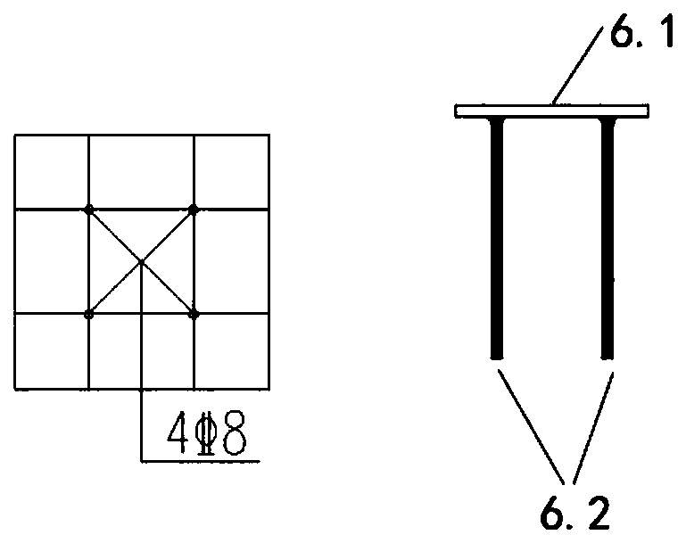
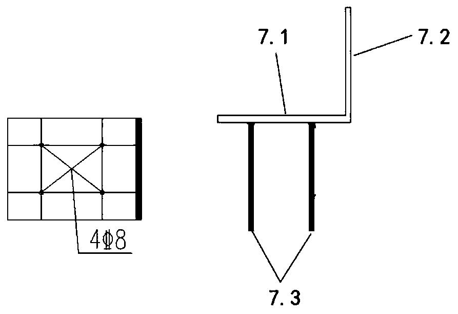
[0026] Refer to attached figure 1 : The specific embodiment of the present invention provides a kind of connection node tha...


PUM


Abstract

The invention provides an external enclosure weight-reduction pre-fabricated wall connecting joint and a construction method thereof. The external enclosure weight-reduction pre-fabricated wall connecting joint comprises a first pre-fabricated double-sided composite wall and a second pre-fabricated double-sided composite wall; the first pre-fabricated double-sided composite wall and the second pre-fabricated double-sided composite wall are spliced in the vertical direction and are connected and fixed through a cast-in-situ beam; inserting ribs and partition boards are disposed at the upper endof the first pre-fabricated double-sided composite wall; the inserting ribs are buried in the first pre-fabricated double-sided composite wall and are partially exposed out of the upper end of the first pre-fabricated double-sided composite wall; the portions, exposed out of the first pre-fabricated double-sided composite wall, of the inserting ribs penetrate through the partition boards to extend into the cast-in-situ beam; a first pre-buried part is buried in the lower end of the second pre-fabricated double-sided composite wall; a second pre-buried part is buried in the upper end of the cast-in-situ beam; the second pre-fabricated double-sided composite wall is fixed to the cast-in-situ beam in a matched mode through the first pre-buried part and the second pre-buried part; and accordingly construction and popularization of a pre-fabricated enclosure wall are facilitated.

Description

technical field [0001] The invention relates to the technical field of prefabricated buildings, in particular to a prefabricated wall connection structure and a construction method thereof. Background technique [0002] With the development of prefabricated buildings, prefabricated double skin walls are increasingly used in prefabricated buildings. It is mentioned in GBT51231-2016, the technical standard structure specification for prefabricated concrete buildings, that traditional prefabricated walls are connected with steel bars to holes, and the vertical connection is realized by integral pouring of concrete. In the actual installation process, it is necessary to insert the steel bars into the corresponding holes. Since the number of steel bars in this connection node is large, and the inner diameter of the hole is only slightly larger than the diameter of the steel bars, it will increase the difficulty of on-site construction, and there are still Concrete grouting is no...

Claims


Application Information

Patent Timeline
Patent Type & Authority Applications(China)
IPC IPC(8): E04B2/64E04B1/41E04C2/04E04C2/06
CPCE04B2/64E04B1/41E04C2/06E04C2/049
Inventor 潘龙吴战飞陆亚珍吴限孟宇航王志刚屈俊峰张少驰袁华安姜卫涛
Owner JIANGSU LONG LEAPING ENG DESIGN
Learn More