An audio receiving chip and audio receiver

An audio receiving and receiver technology, applied in the direction of electrical components, signal processing, loudspeaker signal distribution, etc., can solve problems such as the complexity of the peripheral circuit of the chip, save implementation costs, reduce the degree of signal fading, and eliminate receiving dead zones Effect

Active Publication Date: 2021-03-05
KTMICRO ELECTRONICS
View PDF12 Cites 0 Cited by
  • Summary
  • Abstract
  • Description
  • Claims
  • Application Information

AI Technical Summary

Problems solved by technology

In the existing diversity scheme, two antennas are used to receive the signals of the same wireless microphone respectively, and the two internal audio receiving chips are respectively connected to an antenna, and the microcontroller (MicroController Unit, MCU) reads the signals of the two audio receiving chips. The output received signal strength indication (ReceivedSignal Strength Indication, RSSI) signal generates a control signal according to the size of the RSSI in the two audio receiving chips, and then the audio signal of a certain audio receiving chip is selected by the audio analog switch to output according to the control signal. The solution requires MCU and audio analog switch to participate in output control, which makes the peripheral circuit of the chip more complicated

Method used


Image

  • An audio receiving chip and audio receiver
  • An audio receiving chip and audio receiver
  • An audio receiving chip and audio receiver

Examples


no. 1 example

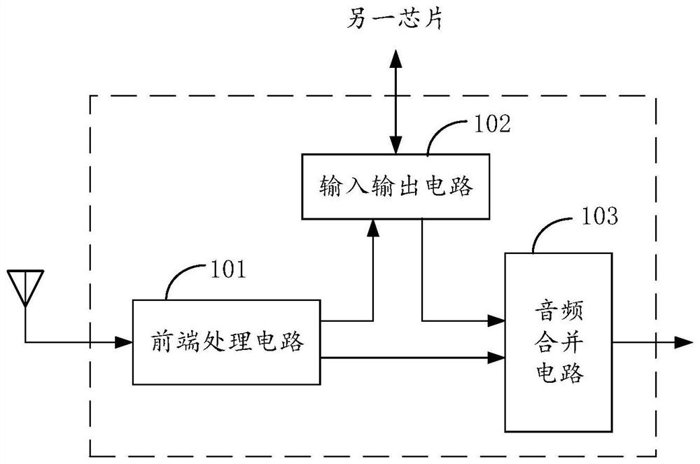
[0042] This embodiment provides an audio receiving chip configured in an audio receiver, refer to figure 2 , the audio receiving chip comprises a front-end processing circuit 101, an input-output circuit 102 and an audio combining circuit 103, and the front-end processing circuit 101 is connected with the antenna of the audio receiver, the input-output circuit 102 and the audio combining circuit 103 respectively, and the input-output circuit 102 is connected to the audio frequency combining circuit 103. The combining circuit 103 is connected. The antenna is used to receive a radio frequency signal, and the front-end processing circuit 101 is used to demodulate the radio frequency signal received by the antenna to obtain a first audio signal carried in the radio frequency signal. The audio receiving chip can be configured in any one of the master mode and the slave mode. When configured in different modes, the input and output circuit 102 and the audio combining circuit 103 wo...

no. 2 example

[0076] This embodiment provides an audio receiving chip, refer to Figure 8 The audio receiving chip includes a front-end processing circuit 101, a framing circuit 104, and an input-output circuit 102. The front-end processing circuit 101 is connected to the antenna of the audio receiver and the framing circuit 104, and the framing circuit 104 is connected to the input-output circuit 102.

[0077] The difference between the audio receiving chip and the audio receiving chip provided by the first embodiment is that the circuit modules that are not used in the slave mode are removed. Therefore, the working principle and optional implementation of each circuit module in the audio receiving chip For the method, refer to the description of the previous embodiment.

[0078] Since the audio receiving chip reduces the number of circuit modules that are turned off in the slave mode, while simplifying the peripheral circuit of the chip, the circuit of the audio receiving chip itself is a...

no. 3 example

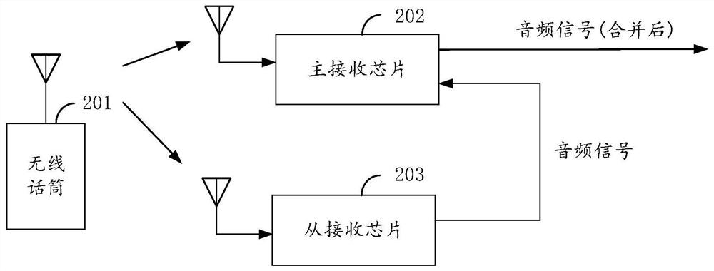
[0083] This embodiment provides an audio receiver, refer to Figure 10 , the audio receiver includes two antennas 301 ; two audio receiving chips 302 ; and an audio output interface 303 . Wherein, each audio receiving chip 302 is used to receive the radio frequency signal transmitted from the corresponding antenna 301, and demodulate the radio frequency signal to obtain the audio signal carried in the radio frequency signal, one of the audio receiving chips in the two audio receiving chips The obtained audio signal and the audio signal from another audio receiving chip are combined and output through the audio combining circuit.

[0084] Optionally, the audio signal output by the audio combining circuit can be a digital audio signal, and the output end of the audio combining circuit can be connected with a digital-to-analog converter, and the digital audio signal is converted into an analog audio signal by the digital-to-analog converter, And it can be output to the sound amp...


PUM


Abstract

The embodiment of the invention provides an audio receiving chip and an audio receiver. The audio receiving chip is arranged on the audio receiver and comprises a front-end processing circuit, an input and output circuit and an audio merging circuit, wherein the front-end processing circuit is respectively connected with an antenna of the audio receiver, the input and output circuit and the audiomerging circuit, the input and output circuit is connected with the audio merging circuit, and the front-end processing circuit is used for demodulating a radio frequency signal received by the antenna to obtain a first audio signal carried in the radio frequency signal. The audio receiving chip can work in a master mode or a slave mode. When operating in master mode, an audio signal of another audio receiving chip working in a slave mode can be received; the two paths of audio signals are combined and output, and the audio signals can be transmitted to the other audio receiving chip working in the master mode when working in the slave mode, so that the signal transmission of the audio signals between the two chips can be realized, an audio analog switch and an MCU are not needed, and theperipheral circuit of the chips is simplified.

Description

technical field [0001] The present application relates to the field of audio technology, in particular, to an audio receiving chip and an audio receiver. Background technique [0002] Wireless microphones are often used in stage performances, KTV, teaching, speeches and other occasions. They are composed of wireless microphones and wireless receivers. In actual use, the multipath effect of wireless channels will cause small-scale fading of the signal, resulting in wireless receiver There is a broken sound, that is, the so-called "frequency drop" phenomenon, especially when it is used indoors, the "frequency drop" phenomenon is more obvious, and antenna diversity is a method to solve the "frequency drop" problem. In the existing diversity scheme, two antennas are used to receive the signals of the same wireless microphone respectively, and the two internal audio receiving chips are respectively connected to an antenna, and the microcontroller (MicroController Unit, MCU) reads...

Claims


Application Information

Patent Timeline
Patent Type & Authority Patents(China)
IPC IPC(8): H04R3/12
CPCH04R3/12H04R2430/00
Inventor 李振王蕊郭爱香亢鹤凯
Owner KTMICRO ELECTRONICS
Why Eureka
Try Eureka