
Display device

一种显示装置、显示面板的技术,应用在电视、彩色电视、照相机等方向,能够解决影响摄像头成像质量与品质、漏光等问题,达到提升视觉冲击效果和产品表现力、扩大屏占比的效果

Inactive Publication Date: 2019-11-08
WUHAN CHINA STAR OPTOELECTRONICS TECH CO LTD
View PDF7 Cites 28 Cited by
  • Summary
  • Abstract
  • Description
  • Claims
  • Application Information

AI Technical Summary

Problems solved by technology

Since the light from the backlight module easily leaks through the edge of the via hole of the upper polarizing film and the lower polarizing film, it affects the image quality and quality of the camera.

Method used


Image

  • Display device

Examples


Embodiment Construction

[0017] Reference in the detailed description to "an embodiment" means that a particular feature, structure, or characteristic described in connection with the embodiment can be included in at least one embodiment of the invention. The same terms appearing in different positions in the specification are not necessarily limited to the same implementation, but should be understood as independent or alternative implementations from other embodiments. Inspired by the technical solutions disclosed in the embodiments provided in the present invention, those skilled in the art should understand that the embodiments described in the present invention may have other combinations or changes of technical solutions consistent with the concept of the present invention.

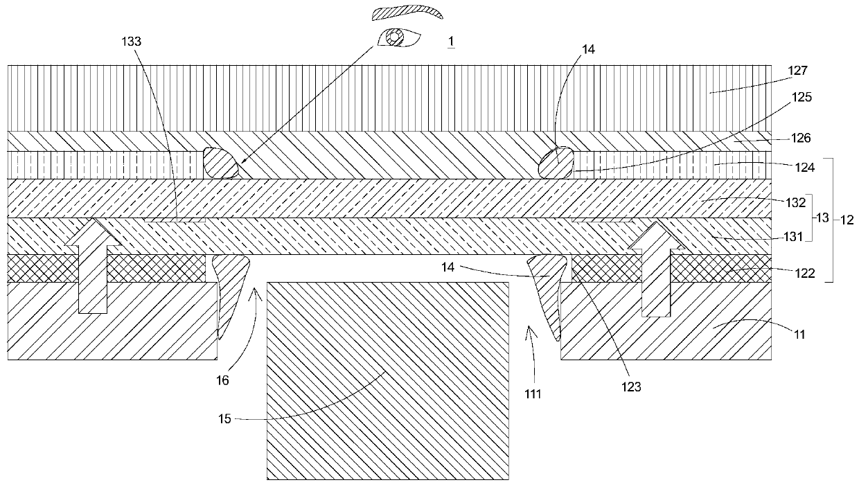
[0018] Please refer to figure 1 as shown, figure 1 It is a schematic cross-sectional view of a display device with an under-display lens of the present invention. As shown in the figure, the present invention provides a d...


PUM


Abstract

The invention discloses a display device which comprises a backlight module and a liquid crystal display module. The backlight module is provided with a through hole. The liquid crystal display modulecomprises a display panel and a lower polarizing film and an upper polarizing film which are arranged on two opposite surfaces of the display panel. The lower polarizing film is provided with a firstvia hole, and the upper polarizing film is provided with a second via hole corresponding to the first via hole, wherein edges of both sides of the second via hole are coated with light shielding parts. Therefore, the risk of side light leakage of the first via hole and the second via hole of the liquid crystal display module is avoided, and an image pick-up effect of an image pick-up module and the market competitiveness are reinforced.

Description

technical field [0001] The invention relates to the technical field of liquid crystal display, in particular to a display device with an under-screen lens. Background technique [0002] With the development of liquid crystal display technology, especially the development of full-screen technology, holes are opened in the display area of ​​display devices (such as tablets, smart phones, etc.), and in-plane cameras (ie, under-screen cameras) are installed to improve the display area. The proportion of demand is getting higher and higher. The existing display device includes a display panel, a backlight module arranged under the display panel, a glass cover arranged above the display panel, and a camera module arranged under the glass cover. The backlight module is also provided with a camera hole to facilitate the installation of the camera module. In addition, the upper and lower polarizing films pasted on the upper and lower surfaces of the display panel also have via hole...

Claims


Application Information

Patent Timeline
Patent Type & Authority Applications(China)
IPC IPC(8): G02F1/1333G02F1/1335G02F1/13357H04N5/225
CPCG02F1/13338G02F1/133528G02F1/133512G02F1/1336H04N23/57G02F2202/28G02F1/133331G02F1/133325G03B30/00G03B11/045G03B17/02H04N23/53G02F1/133514G02F1/1368
Inventor 张鹏
Owner WUHAN CHINA STAR OPTOELECTRONICS TECH CO LTD
Learn More