A safety protection device
A technology of safety protection device and gate device, which is applied to power devices, instruments, alarms and other directions inside the switch, can solve problems such as easy forgetting, and achieve the effect of high stability
- Summary
- Abstract
- Description
- Claims
- Application Information
AI Technical Summary
Problems solved by technology
Method used
Image
Examples
Embodiment 1
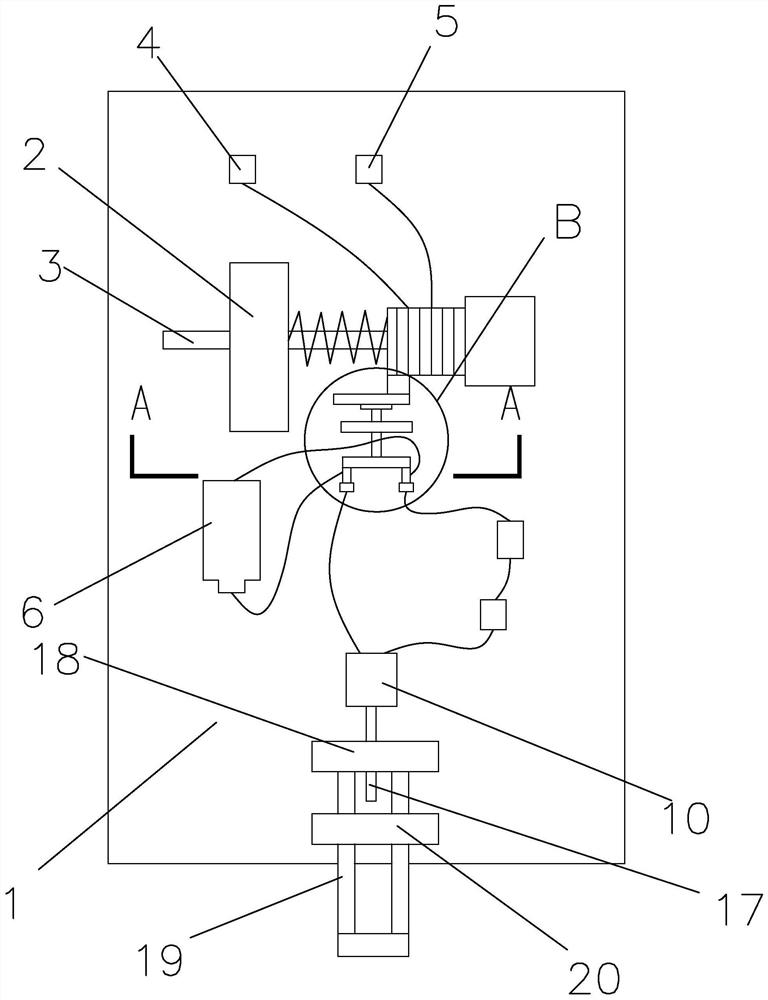
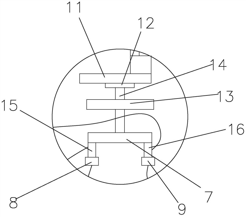
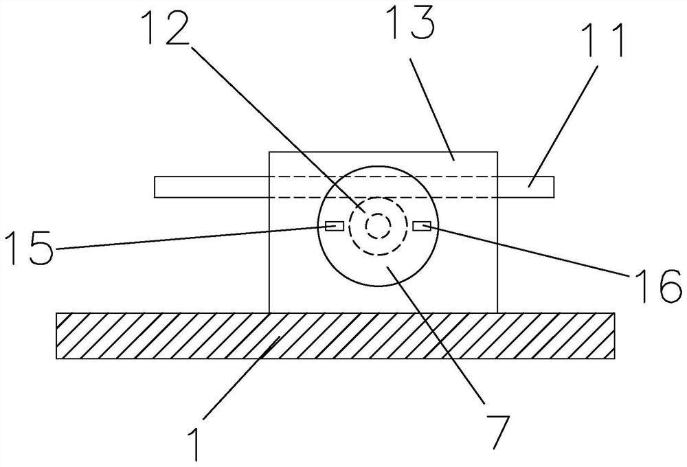
[0022] Figure 1 to Figure 4 It is a safety protection device, comprising a base 1, a support base 2 is fixedly connected to the base 1, a guide rod 3 is inserted on the support base 2, and the guide rod 3 is slidably connected with the support base 2. One end of the guide rod 3 is fixedly connected with an electromagnet, and the guide rod 3 is covered with a tension spring, and one end of the tension spring leans against the support seat 2, and the other end of the tension spring leans against the electromagnet. The electromagnet is connected with a positive pole 4 and a negative pole 5, and the side of the electromagnet away from the guide rod 3 is provided with a magnet, and the magnet is fixedly connected to the base 1, and the base 1 is provided with a push gate device. When the power is on, the gate pushing device pushes down the electric gate; the gate pushing device includes a battery 6, a switch plate 7, a first electrode 8, a second electrode 9, a third electrode 15,...
Embodiment 2
[0027] Figure 5 , Image 6 As shown, the general situation of this embodiment is consistent with that of Embodiment 1, the difference is that the push gate device includes a first electrode 8, a second electrode 9, a battery 6, and an electric push rod 21 for pushing down an electric switch. The first electrode 8 is fixed on the electromagnet, the second electrode 9 is fixed on the base 1, the second electrode 9 is located on the movement path of the first electrode 8, and one pole of the battery 6 is connected to the second electrode. 9 is electrically connected, the other pole of the battery 6 is electrically connected to one pole of the electric push rod 21, and the other pole of the electric push rod 21 is electrically connected to the first electrode 8; the circuit where the electric push rod 21 is located is connected in series There is a delay relay 22; an alarm is connected in series on the circuit where the electric push rod 21 is located.
[0028] The process used...
PUM
 Abstract
Description
Claims
Application Information
 - R&D
- Intellectual Property
- Life Sciences
- Materials
- Tech Scout
- Unparalleled Data Quality
- Higher Quality Content
- 60% Fewer Hallucinations
Browse by: Latest US Patents, China's latest patents, Technical Efficacy Thesaurus, Application Domain, Technology Topic, Popular Technical Reports.
© 2025 PatSnap. All rights reserved.Legal|Privacy policy|Modern Slavery Act Transparency Statement|Sitemap|About US| Contact US: help@patsnap.com


