

Surgical nursing medical box
A medical box and surgical technology, applied in the field of medical equipment, can solve the problems of non-sealed partitions, cross-infection of medical equipment, and infection of medical equipment, so as to avoid random placement and mutual cross-infection
- Summary
- Abstract
- Description
- Claims
- Application Information
AI Technical Summary
Benefits of technology
Problems solved by technology
Method used
Image

Examples
Embodiment 1
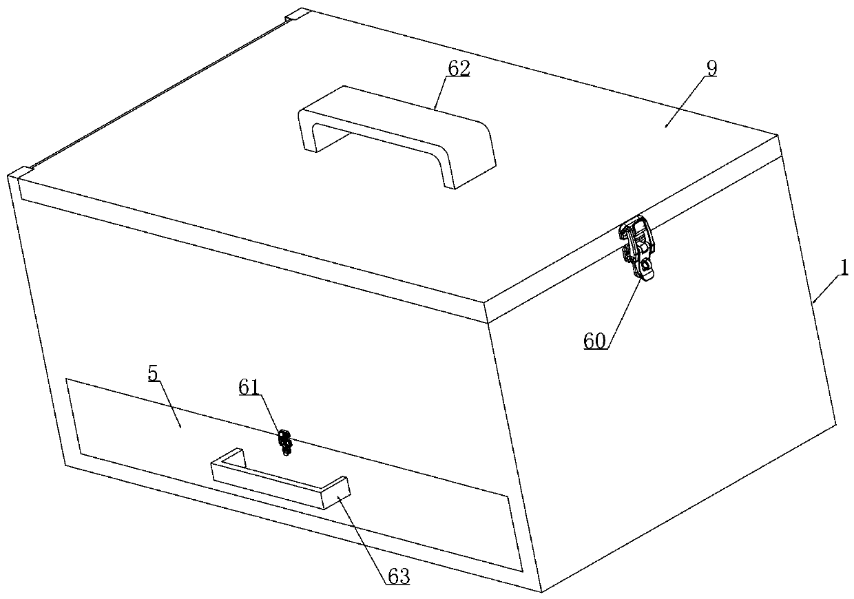
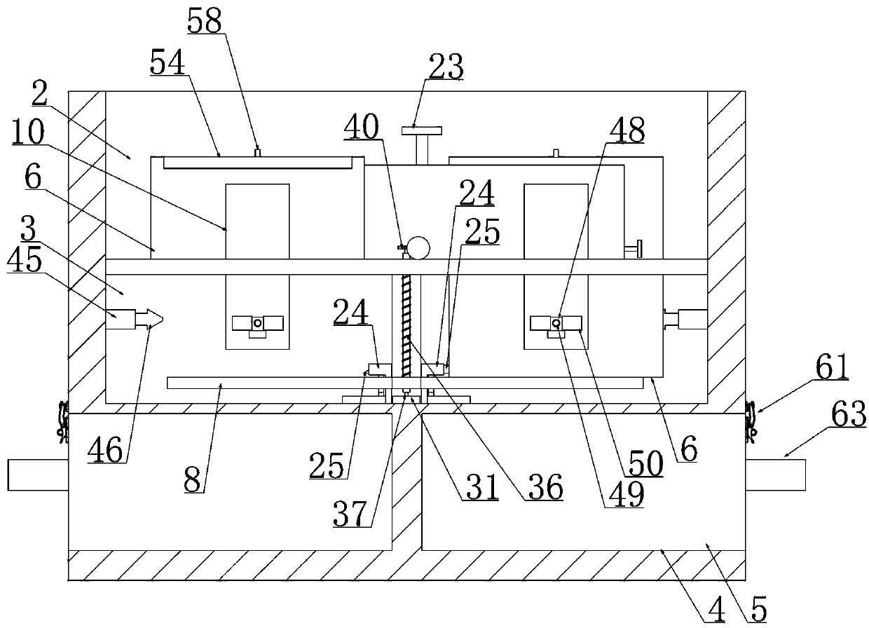
[0049] Embodiment 1, a surgical nursing medical box, comprising a box body 1, characterized in that a cleaning chamber 2, a disinfection chamber 3, and a collection chamber 4 are arranged vertically in the box body 1, and the collection chamber 4 is provided with There is a collection box 5, a number of storage boxes 6 are arranged in the cleaning chamber 2 and the storage boxes 6 are vertically slidably connected in the box body 1, and the bottom wall of the cleaning chamber 2 is provided with a control for controlling the position of the storage boxes 6 device and the bottom wall of the cleaning chamber 2 is provided with a leakage hole 7 matched with the storage box 6, and the longitudinal side walls of the disinfection box are fixed with a primary disinfection device and the storage box 6 faces the box body 1 close to it. One end of the longitudinal side wall is provided with an opening and closing device, and when the storage box 6 slides down into the disinfection box, th...
Embodiment 2
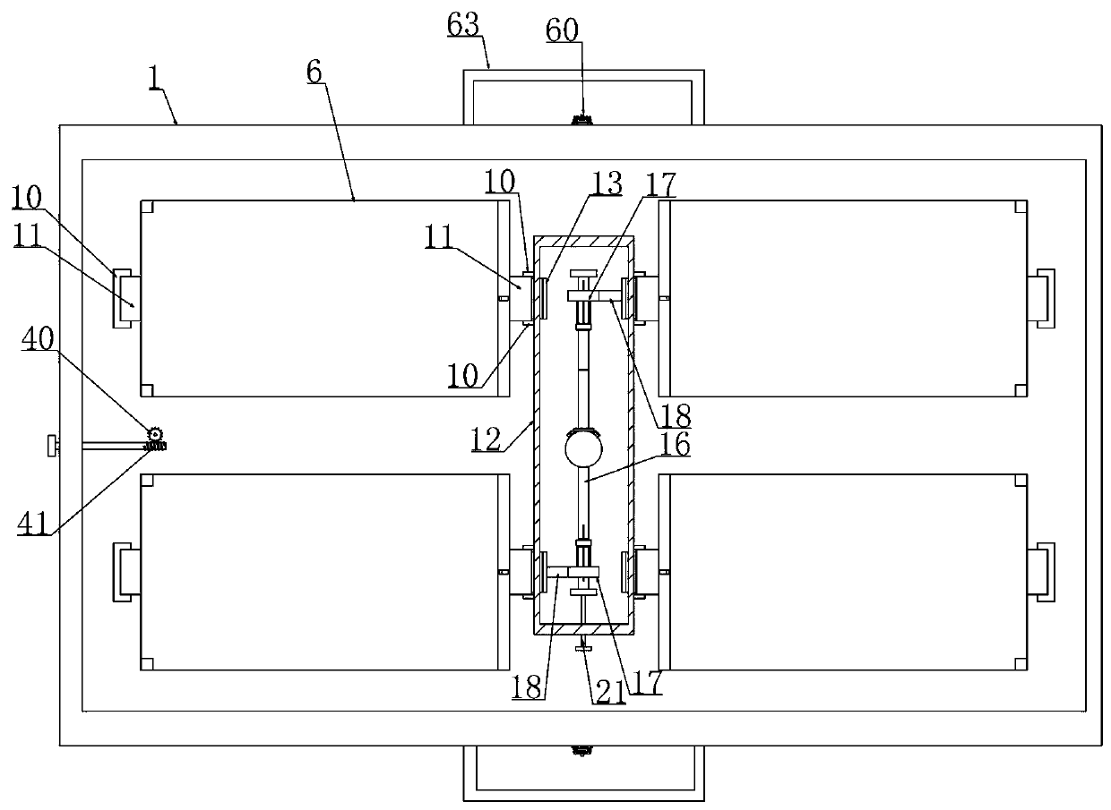
[0055] Embodiment 2, on the basis of Embodiment 1, the bottom wall of the cleaning chamber 2 is provided with a slide rail 10 matched with the storage box 6, and the lateral sides of the storage box 6 are respectively vertically slidably connected by sliders 11 In the slide rail 10, the slide rail 10 extends downward into the disinfection chamber 3, and the control device is arranged in the lock box 12 fixed on the bottom wall of the clean chamber 2. The control device includes: a slide block 11 facing the side of the lock box 12 A telescopic block 13 is slidably connected in the interior and is connected through a return spring 14 between the telescopic block 13 and the slide block 11. The side wall of the locking box 12 is provided with a rectangular hole 15 slidingly matched with the telescopic block 13, and the telescopic block 13 extends into the The upper and lower ends of one side and the bottom wall of the rectangular hole 15 in the locking box 12 are all set as slopes,...
Embodiment 3
[0058]Embodiment 3, on the basis of Embodiment 2, the withdrawal device includes: a rotating shaft 16 extending longitudinally is installed in the locking box 12, and the two longitudinal ends of the rotating shaft 16 are respectively axially slidably connected with one-way bearings 17 with the shaft center , the installation directions of the two one-way bearings 17 are opposite, and the outer surface of the one-way bearing 17 is fixedly connected with a withdrawal rod 18 extending along its diameter direction, and the end of the withdrawal rod 18 away from the one-way bearing 17 is set as a slope, and the one-way bearing 17 The coaxial center is rotated at intervals with rings 19, and the rings 19 are rotatably mounted on the mobile frame 20 that is longitudinally slidably connected to the bottom wall of the lock box 12, and the two mobile frames 20 are mounted in the lock box 12 through screw fit and rotation. The driving screw 21, the rotating shaft 16 is driven by the hand...
PUM
 Abstract
Description
Claims
Application Information