Dynamic planning method for unmanned aerial vehicle path based on two-dimensional and three-dimensional integration

A dynamic planning and unmanned aerial vehicle technology, applied in the field of unmanned aerial vehicles, can solve the problems of lack of UAV path height safety constraints, lack of height safety constraints of two-dimensional dynamic path planning, UAV differences, etc. Effectiveness and planning efficiency are improved, dynamic planning efficiency is improved, and safety constraints are improved.

Active Publication Date: 2019-11-22
CHUZHOU UNIV +1
View PDF8 Cites 5 Cited by
  • Summary
  • Abstract
  • Description
  • Claims
  • Application Information

AI Technical Summary

Problems solved by technology

[0004] (1) Two-dimensional dynamic path planning lacks high security constraints
[0005] Although the two-dimensional path dynamic planning is higher than the three-dimensional path dynamic planning in terms of search space efficiency, it is only used in theoretical aspects because it lacks the high security constraints of the UAV path and is quite different from the real path of the UAV. There is a big difference between research and practical application
[0006] (2) 3D dynamic path planning search space efficiency is low
[0007] Although the current dynamic planning of 3D UAV paths satisfies the high security constraints of the real path of UAVs, on the one hand, due to the increase of high security constraints, the search space efficiency increases exponentially; There is a big difference between the planning environment and the real environment, and most UAV path planning is to calculate the path set through the relevant three-dimensional path algorithm, and then manually correct the waypoints on the spot

Method used


Image

  • Dynamic planning method for unmanned aerial vehicle path based on two-dimensional and three-dimensional integration
  • Dynamic planning method for unmanned aerial vehicle path based on two-dimensional and three-dimensional integration
  • Dynamic planning method for unmanned aerial vehicle path based on two-dimensional and three-dimensional integration

Examples


Embodiment Construction

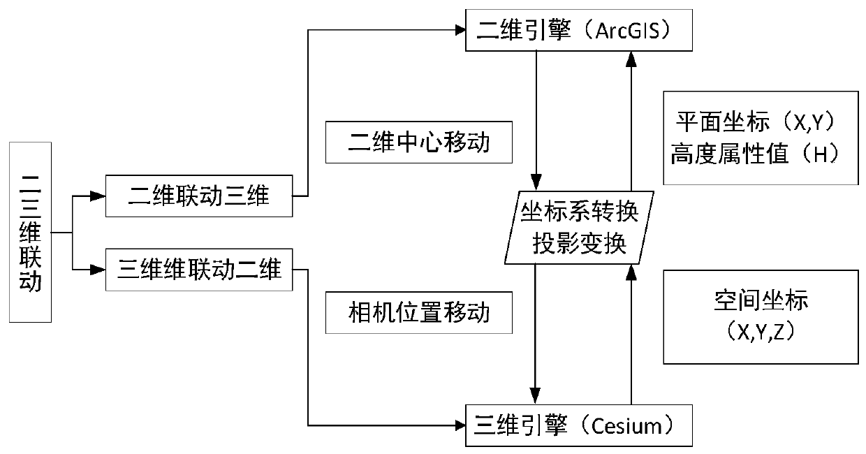
[0037] The method of the present invention first performs oblique photographic modeling on the path planning area of ​​the UAV, and then based on the 2D and 3D integration technology, such as figure 1 As shown, the initial path of the UAV that satisfies the kinematic constraints is planned in the two-dimensional map window, and at the same time, the oblique photographic model is realized in the three-dimensional full-element real-scene map window with the visibility algorithm and the limited surface analysis algorithm in the GIS aerial analysis function The three-dimensional path of the UAV in satisfies the security constraints, and the specific implementation steps are as follows:

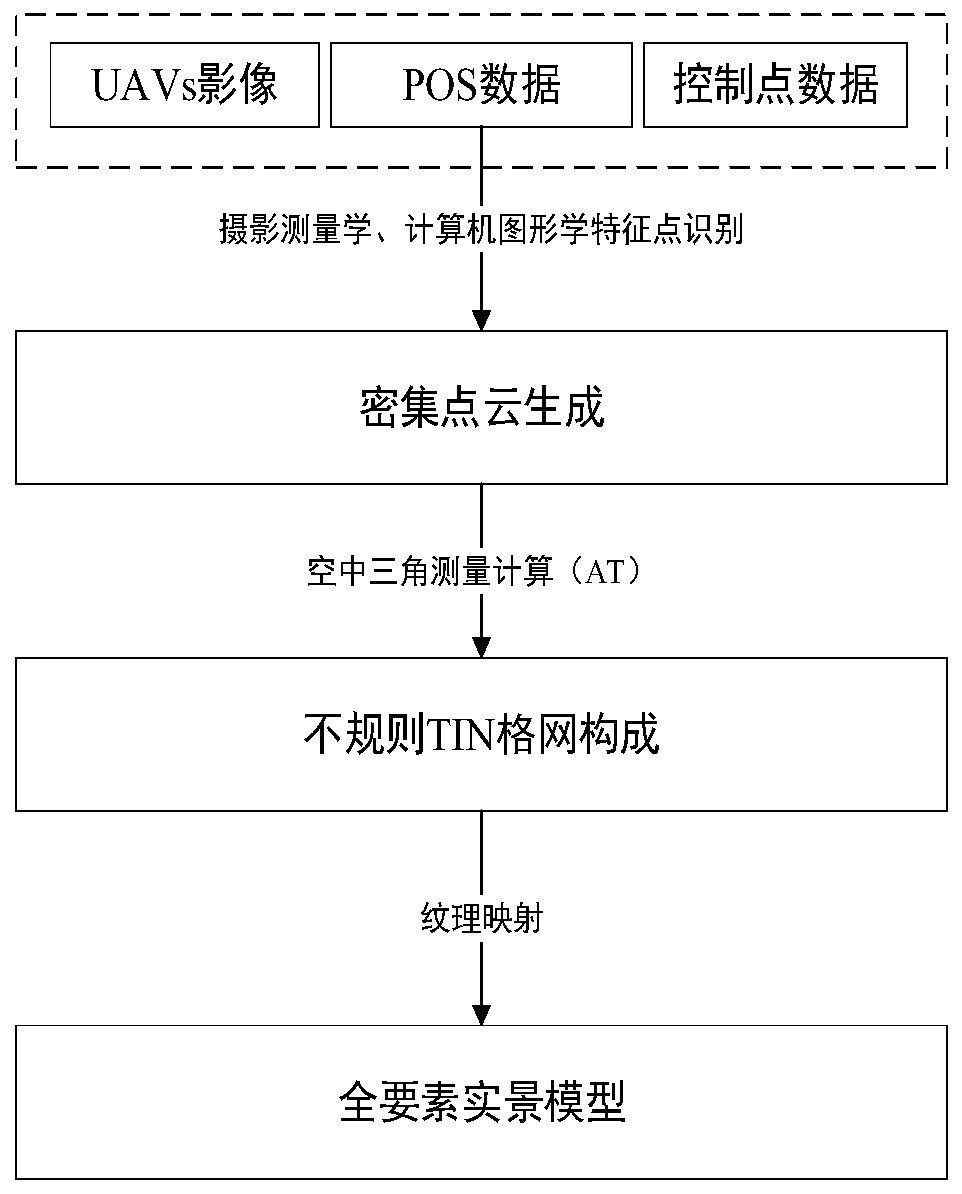
[0038] (1) Oblique photographic modeling of the UAV path planning area

[0039] With the development of photogrammetry and computer graphics, "digital earth" has become a trend and gradually formed. The current oblique photography technology realizes rapid real-world modeling of the survey area t...


PUM


Abstract

The invention provides a dynamic planning method for an unmanned aerial vehicle path based on two-dimensional and three-dimensional integration. The method comprises the steps of 1, carrying out oblique photography modeling on an unmanned aerial vehicle path planning area; 2, planning an initial unmanned aerial vehicle path and a height attribute value in a two-dimensional map window; 3, judging whether a waypoint in a three-dimensional map window is outside the ground object or not based on a GIS limiting surface analysis algorithm; 4, judging the intervisibility among the waypoints in the three-dimensional map window based on a GIS intervisibility algorithm; 5, judging whether the new waypoint is outside the ground object or not in the three-dimensional map window; and step 6, obtainingthe waypoint position and height attribute value of the unmanned aerial vehicle path in the two-dimensional map window. Compared with the traditional unmanned aerial vehicle path planning method, themethod provided by the invention can meet the safety requirement of the unmanned aerial vehicle path in a complex real environment on the one hand, and can greatly improve the unmanned aerial vehiclepath planning efficiency on the other hand.

Description

technical field [0001] The invention belongs to the technical field of unmanned aerial vehicles, and in particular relates to a dynamic planning method for an unmanned aerial vehicle path based on two-dimensional and three-dimensional integration. Background technique [0002] On the one hand, with the development of parallel computing and computer graphics, the oblique photographic model produced by UAV aerial photogrammetry is widely used in land planning, resource surveying, " Digital Earth" and other fields. On the other hand, the idea of ​​integration between two-dimensional maps and three-dimensional scene maps was first applied in military training, and its purpose is to solve the problem of disorientation caused by soldiers in the virtual environment. 2D and 3D linkage technology is based on the visualization of 2D electronic map and 3D electronic map, and realizes the two-way communication between the 2D electronic map and the corresponding 3D virtual scene. , so ...

Claims


Application Information

Patent Timeline
IPC IPC(8): G05D1/10
CPCG05D1/101
Inventor 曾微波童矿
Owner CHUZHOU UNIV
Why Eureka
Try Eureka