
Dehumidification monitoring system applied to transformer station cable trench

A monitoring system and substation technology, applied in the control/regulation system, humidity control, non-electric variable control and other directions, can solve the problems of substation cable trench moisture, switch cabinet condensation and other problems, to solve the problem of moisture, avoid condensation and discharge, Effects of addressing adverse effects

Pending Publication Date: 2019-11-22
JIANGSU ELECTRIC POWER CO +1
View PDF0 Cites 3 Cited by
  • Summary
  • Abstract
  • Description
  • Claims
  • Application Information

AI Technical Summary

Problems solved by technology

[0004] The invention aims to solve the problems of moisture in the cable trench of the substation and condensation in the switchgear, and provides a systematic dehumidification monitoring system for the cable trench of the substation to solve such problems

Method used


Image

  • Dehumidification monitoring system applied to transformer station cable trench
  • Dehumidification monitoring system applied to transformer station cable trench
  • Dehumidification monitoring system applied to transformer station cable trench

Examples


Embodiment Construction

[0022] In order to make the objectives, technical solutions and advantages of the present invention clearer, the technical solutions in the embodiments of the present invention will be described in more detail below in conjunction with the drawings in the embodiments of the present invention. In the drawings, the same or similar reference numerals denote the same or similar elements or elements having the same or similar functions throughout. The described embodiments are some, but not all, embodiments of the invention. The embodiments described below by referring to the figures are exemplary and are intended to explain the present invention and should not be construed as limiting the present invention. Based on the embodiments of the present invention, all other embodiments obtained by persons of ordinary skill in the art without making creative efforts belong to the protection scope of the present invention. Embodiments of the present invention will be described in detail b...


PUM


Abstract

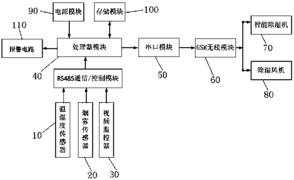
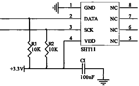
The system is applied to a dehumidification monitoring system applied to a transformer station cable trench. The system comprises a sensor assembly, a processor module, a GSM wireless module and dehumidification equipment, wherein the sensor assembly comprises a temperature and humidity sensor, the dehumidification equipment comprises an upper dehumidification system and a lower dehumidification system, the temperature and humidity sensor is connected with the processor module through an RS485 communication interface, the processor module is connected with the GSM wireless module through a serial port module, the GSM wireless module is connected with the upper dehumidification system and the lower dehumidification system, the upper dehumidification system is installed in a transformer station machine room, the lower dehumidification system is installed in a cable trench of the transformer substation machine room, the dry air is replaced by the lower dehumidification system in the cabletrench to enter the cable trench, moisture is discharged into the transformer station machine room through circulation, the moisture is compressed into the water through the upper dehumidification system in the transformer station machine room to be discharged out of the room, and the dry air enters the cable trench to be circulated in a reciprocating mode. The system is advantaged in that a moisture problem of a switch cabinet can be fundamentally solved, and accidents such as condensation discharge of the switch cabinet, reduction of cable insulation, explosion of the switch cabinet and thelike are effectively avoided.

Description

technical field [0001] The invention relates to a monitoring system for the operating environment of a cable trench in a substation, in particular to a novel cable trench dehumidification monitoring system. Background technique [0002] The equipment in the substation shoulders very important tasks in the power grid. Among them, the primary cables, main equipment, and secondary equipment are important components of the substation, but they are easily affected by external environmental factors, such as water accumulation in the cable trench. During the rainy season and the alternation of day and night, due to the change of relative humidity and temperature difference, it is very easy to cause indoor dampness, resulting in condensation inside and outside the equipment, which leads to the decline of equipment insulation, resulting in poor contact of terminals, damage to relay contacts inside the equipment, DC grounding, and discharge of switch cabinets. Insulation breakdown lea...

Claims


Application Information

Patent Timeline
Patent Type & Authority Applications(China)
IPC IPC(8): G05D22/02
CPCG05D22/02
Inventor 李亚会倪建勋陈飞宇师珂段庆权王晓辉何成宝
Owner JIANGSU ELECTRIC POWER CO
Learn More