Stapling machine

A stapler and sheath technology, applied in the field of staplers, can solve problems such as damage, too fast, too strong, and damage

Inactive Publication Date: 2019-11-26
PAO SHEN ENTERPRISES
View PDF9 Cites 0 Cited by
  • Summary
  • Abstract
  • Description
  • Claims
  • Application Information

AI Technical Summary

Problems solved by technology

[0003] However, in order to allow the middle branch 14 to pop out quickly, the compression spring with larger elastic force can be set, but if the elastic force design of the compression spring is too large, the middle branch 14 may be too fast and too fast. Strong force pops out, once it accidentally hits the user or object, it will cause damage and damage

Method used


Image

  • Stapling machine
  • Stapling machine
  • Stapling machine

Examples


Embodiment Construction

[0030] The present invention will be described in detail below in conjunction with the accompanying drawings and embodiments.

[0031] Before the present invention is described in detail, it should be noted that in the following description, similar elements are denoted by the same numerals.

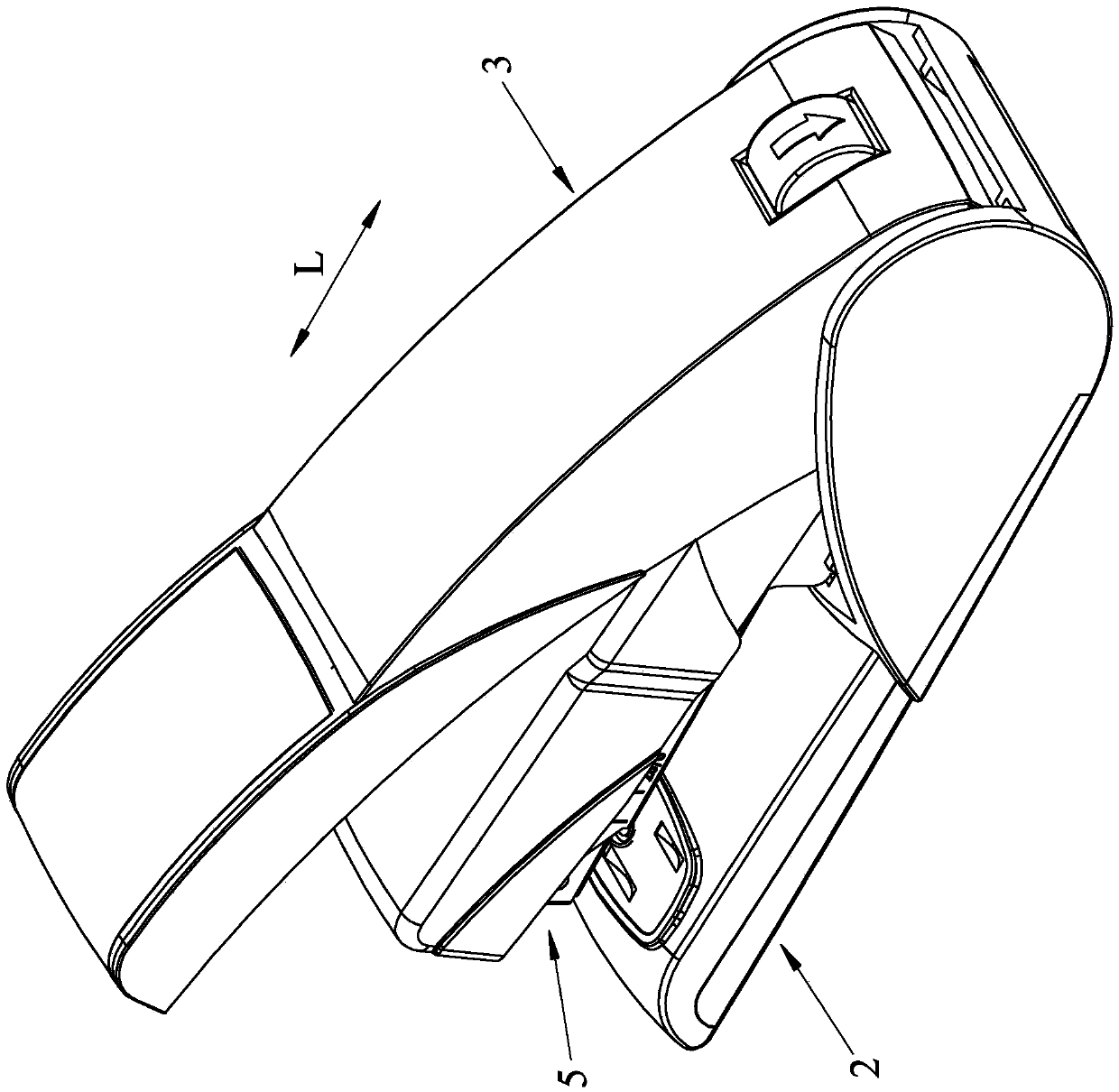
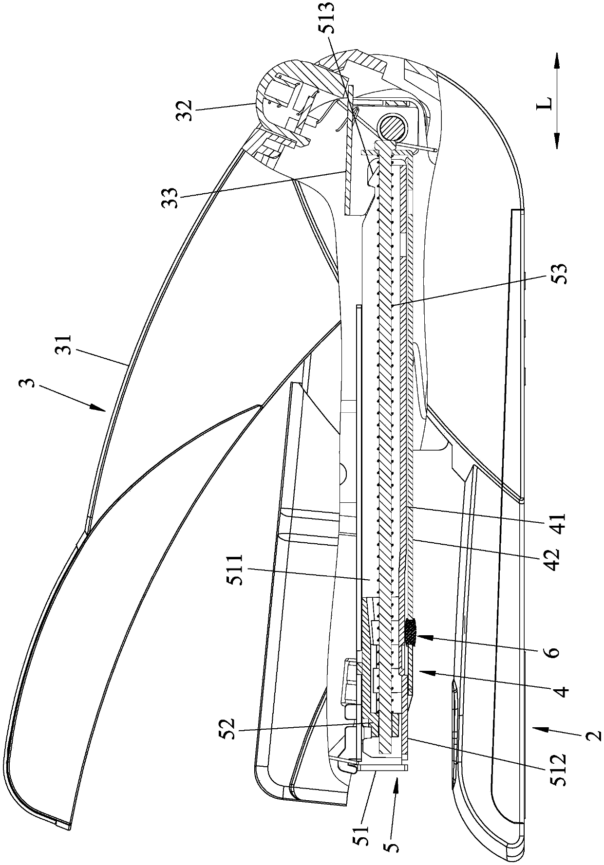
[0032] refer to figure 2 and image 3 , a first embodiment of the stapler of the present invention, defined image 3 The center left is a front, and defines image 3 The middle right is a rear opposite to the front, and the first embodiment includes a base 2 , a handle module 3 , a sheath 4 , a middle branch module 5 , and a buffer elastic member 6 .

[0033] The handle module 3 includes a handle 31 , a pressing member 32 disposed on the handle 31 , and a positioning member 33 that is abutted against by the pressing member 32 and rotates.

[0034] refer to image 3 , Figure 4 and Figure 5 , the sheath 4 extends along a front-rear direction L and is pivotally mounted on the base...


PUM


Abstract

The invention discloses a stapling machine which comprises a base, a protection sleeve, a middle support module and a buffering elastic part. The protection sleeve comprises a middle support space anda protection sleeve bottom wall. The middle support module comprises a middle support which can be movably arranged in the middle support space in the front-back direction, and the middle support canmove between the first position and the second position relative to the protection sleeve and is provided with a middle support bottom wall. The buffering elastic part comprises an arrangement end and a friction end, wherein the friction end is used for providing friction force between the protection sleeve and the middle support when the middle support moves in the front-back direction. An arrangement part for the arrangement of the arrangement end is arranged on one of the protection sleeve bottom wall and the middle support bottom wall, and a first sliding groove, a first inclined guide groove and a first stop face for the friction end to slide are sequentially formed in the other one of the protection sleeve bottom wall and the middle support bottom wall. Thus, buffering can be provided when the middle support is bounced out, and the risk caused by accidental colliding on a user is avoided.

Description

technical field [0001] The invention relates to a stationery, in particular to a stapler. Background technique [0002] Such as figure 1 As shown, it is an existing stapler, which includes a base 11, a handle 12 pivotally connected to the base 11, a sheath 13 arranged on the base 11, and a movably arranged on the base 11. The middle branch 14 of the sheath 13 and the handle 12 have a button 121 . When the user wants to place or replace a staple, he can press the button 121, and utilize the elastic force of a compression spring (not shown) arranged between the sheath 13 and the middle branch 14 to make the The middle branch 14 ejects the sheath 13 forward, allowing the user to place or replace the staples inside the middle branch 14 . [0003] However, in order to allow the middle branch 14 to pop out quickly, the compression spring with larger elastic force can be set, but if the elastic force design of the compression spring is too large, the middle branch 14 may be too ...

Claims


Application Information

Patent Timeline
Patent Type & Authority Applications(China)
IPC IPC(8): B25C5/02
CPCB25C5/025
Inventor 周俊斌张峻维
Owner PAO SHEN ENTERPRISES
Why Eureka
Try Eureka