Suspension roller type cement pipe making machine

A pipe making machine and hanging roller technology, which is applied in the field of hanging roller cement pipe making machines, can solve the problems of insufficient bearing weight of the hanging roller shaft and sagging downward, and achieves the effect of high work efficiency and improved safety.

Active Publication Date: 2019-11-26
唐山市丰南区利源水泥制品有限公司
View PDF7 Cites 3 Cited by
  • Summary
  • Abstract
  • Description
  • Claims
  • Application Information

AI Technical Summary

Problems solved by technology

[0004] At present, in the existing suspension roller cement pipe making machine, when the door frame is opened to install the outer mold, the end of the suspension roller shaft close to the door frame is in a suspended state, and the support seat at the tail end is not enough to bear the weight of the suspension roller shaft, and the suspension roller shaft is close to the door. One end of the rack will hang down due to gravity

Method used


Image

  • Suspension roller type cement pipe making machine
  • Suspension roller type cement pipe making machine
  • Suspension roller type cement pipe making machine

Examples


Embodiment 1

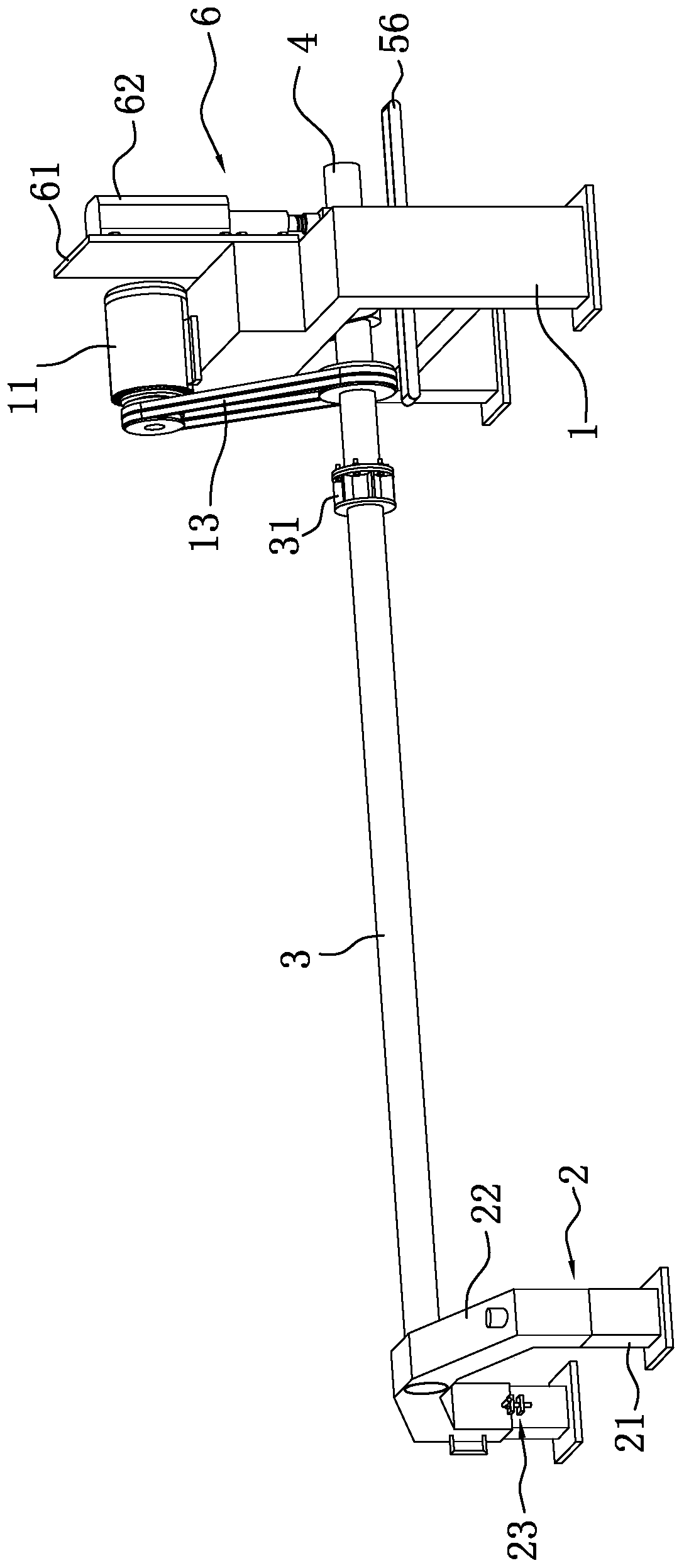
[0037] Embodiment one: a kind of suspended roller cement pipe making machine, such as figure 1 and figure 2 As shown, it includes a frame 1, a door frame 2, a suspension roller shaft 3, a driving shaft 4 and a feeding device 5. A drive motor 11 is fixedly installed above the frame 1, a shaft support seat 12 is arranged below the frame 1, and a drive shaft 4 is fixedly installed in the shaft support seat 12, and the drive shaft 4 rotates through the drive motor 11 linkage belt 13, and the suspension roller shaft 3 One end close to the frame 1 is fixed on the driving shaft 4 through a flange 31, the other end of the suspension roller shaft 3 is rotationally connected with the door frame 2, and the suspension roller shaft 3 rotates with the driving shaft 4 to work. The feeding device 5 is arranged outside the hanging roller cement pipe making machine, and the feeding device 5 can provide the concrete for pipe making for the hanging roller cement pipe making machine.

[0038] l...

Embodiment 2

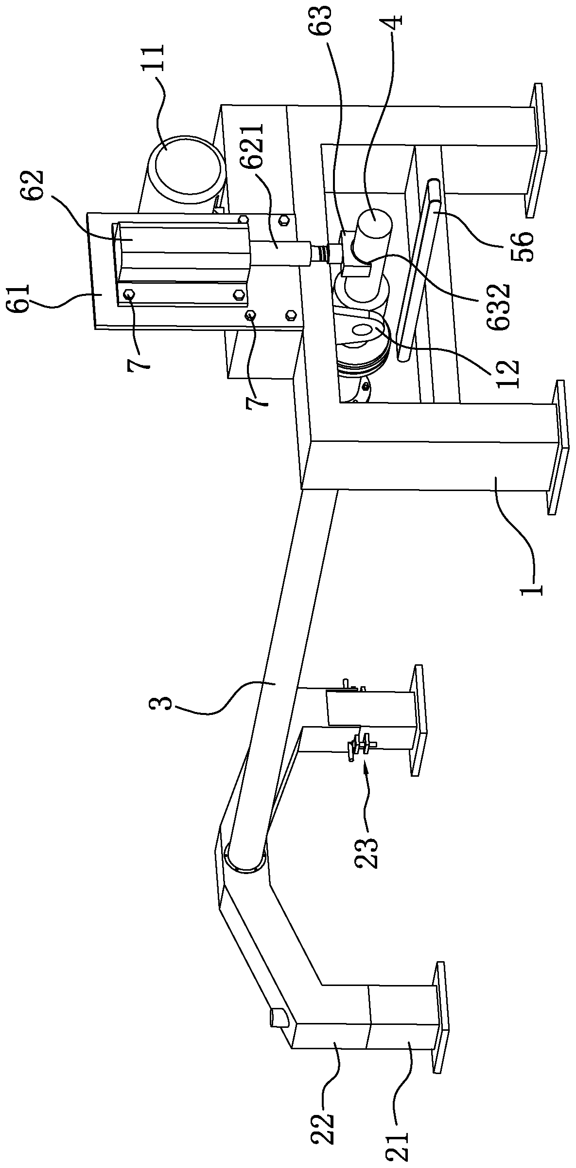
[0046] Embodiment 2: A suspension roller cement pipe making machine, the difference from Embodiment 1 is that, as Figure 7 As shown, the pressing device 6 includes a base plate 61 and a drive mechanism installed and fixed on the base plate 61. The base plate 61 is connected and installed on the frame 1 by bolts 7. The drive mechanism is a control motor 64, and the control motor 64 is connected to the base plate by bolts 7. 61, the control motor 64 is connected with a screw 65, the base plate 61 is provided with two support blocks 651, the screw 65 is rotatably connected in the two support blocks 651, the screw 65 is threadedly connected with a slide block 652, the middle position of the slide block 652 Threaded holes are provided, the two sides of the slider 652 are respectively provided with support rods 66 fixed on the bottom plate 61, and the two sides of the slider 652 are provided with through holes, the through holes on the slider 652 can accommodate the support rods 66 ...


PUM


Abstract

The invention relates to a suspension roller type cement pipe making machine, and relates to the technical field of cement pipe making machines. The suspension roller type cement pipe making machine comprises a rack, a door frame, a suspension roller shaft and a driving shaft, wherein one end of the suspension roller shaft is connected with the driving shaft through a flange plate, the other end of the suspension roller shaft is connected with the door frame in a rotating mode, and the driving shaft is installed on the rack through a shaft supporting seat; and the suspension roller type cementpipe making machine further comprises a downward pressing device fixedly installed on the rack, wherein the downward pressing device comprises a bottom plate, a driving mechanism and a pressing platearranged on the driving mechanism, the pressing plate is arranged above the end, far away from the suspension roller shaft, of the driving shaft, the driving mechanism is arranged on the bottom plate, and the bottom plate is arranged on the rack. The machine has the effect of controlling the suspension roller shaft to be in a horizontal state.

Description

technical field [0001] The invention relates to the technical field of cement pipe making machines, in particular to a hanging roller cement pipe making machine. Background technique [0002] At present, the cement pipe making machine can be divided into hanging roller cement pipe making machine and centrifugal cement pipe making machine according to its structure. The hanging roller cement pipe making machine is composed of main motor, transmission mechanism, feeding mechanism, main frame, main transmission Shaft, stick shaft, movable door frame and other components. [0003] The Chinese patent with the existing notification number CN206351491U discloses a suspended roller cement pipe making machine, which includes a frame, a suspended roller shaft and a door frame; the frame includes a support column and a fixed beam; one end of the fixed beam is fixed to the support column Connection, the other end of the fixed beam is a free end, and a free filling area is formed on one...

Claims


Application Information

Patent Timeline
Patent Type & Authority Applications(China)
IPC IPC(8): B28B21/32B28B17/00
CPCB28B17/0063B28B21/32
Inventor 董延
Owner 唐山市丰南区利源水泥制品有限公司
Why Eureka
Try Eureka