Sealed high-voltage direct current relay

A high-voltage direct current, sealed technology, applied in the direction of relays, electromagnetic relays, high-voltage air circuit breakers, etc., can solve the problems of the winding space of the magnetic circuit part becoming smaller, affecting the performance of the magnetic circuit, affecting the insulation distance, etc., to achieve the winding space Maximize and improve the magnetic circuit performance and avoid the effect of insulation performance deterioration

Pending Publication Date: 2019-11-26
XIAMEN HONGFA ELECTRIC POWER CONTROLS
View PDF0 Cites 0 Cited by
  • Summary
  • Abstract
  • Description
  • Claims
  • Application Information

AI Technical Summary

Problems solved by technology

In order to make the volume as small as possible, this high-voltage DC relay in the prior art is usually designed in a circular shape (that is, the yoke iron plate, coil, etc. are circular), while the ceramic cover is roughly rectangular. There are two ways to connect the exhaust pipe of the relay. One is to install the exhaust pipe on the ceramic cover, usually at the offset position in the middle of the connection between the two load terminals, and the upper end of the exhaust pipe is exposed. Outside the ceramic cover, the lower end of the exhaust pipe extends into the cavity of the ceramic cover. Since the exhaust pipe is made of copper, the exhaust pipe between the two load terminals will affect the insulation distance between the two load terminals. The other is to install the exhaust pipe in the magnetic circuit part. Specifically, the exhaust pipe is installed at the yoke iron plate, the lower part of the exhaust pipe is at the winding window of the coil, and the upper end of the exhaust pipe extends Into the cavity of the ceramic cover above the yoke iron plate, so that the disadvantage of the winding space of the magnetic circuit part becomes smaller, which affects the magnetic circuit performance of the product

Method used


Image

  • Sealed high-voltage direct current relay
  • Sealed high-voltage direct current relay
  • Sealed high-voltage direct current relay

Examples


Embodiment

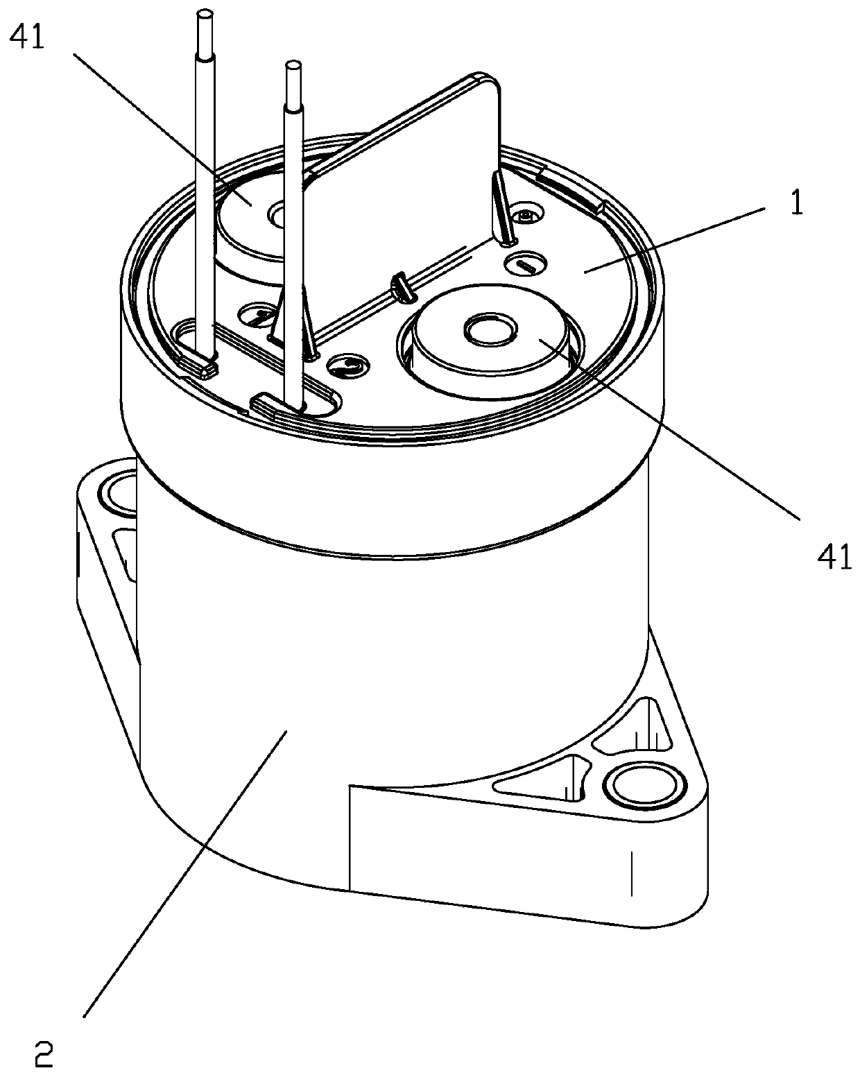
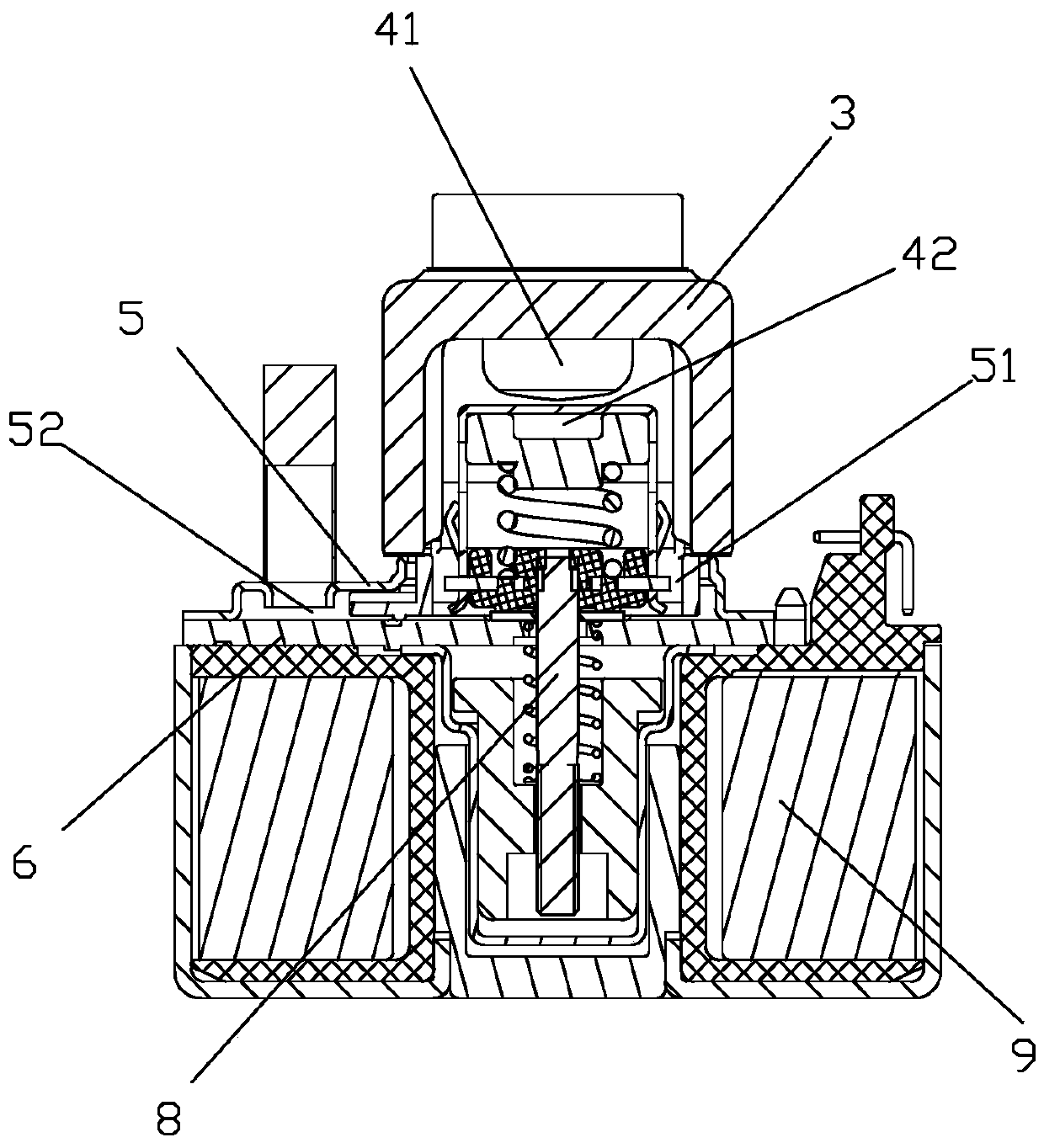
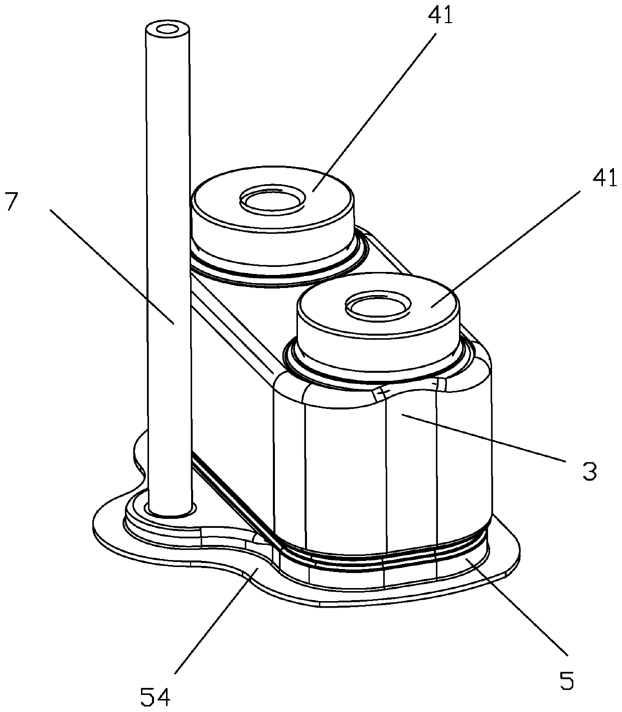
[0028] See Figure 1 to Figure 14 As shown, a sealed high-voltage DC relay of the present invention includes a cover plate 1, a base 2, a ceramic cover 3, two load lead-out ends 41, a movable spring 42, a metal frame sheet 5, a yoke plate 6, and copper The exhaust pipe 7, the pushing part 8, and the coil 9 are components; among them, the ceramic cover 3 is roughly rectangular, and the yoke plate 6 is roughly circular; the two load lead-out ends 41 (ie, static contact lead-out ends) are respectively Installed on the top wall of the ceramic cover 3, the bottom ends of the two load lead-out ends 41 respectively extend into the cavity of the ceramic cover and cooperate with the movable spring 42. The movable spring 42 is installed at one end of the pushing part 8, and the pushing part 8 The other end is matched with the coil; the peripheral dimension of the top end of the metal frame piece 5 is matched with the peripheral dimension of the bottom end of the ceramic cover 3, and the ...


PUM


Abstract

The invention discloses a sealed high-voltage direct current relay, comprising a ceramic cover, two load leading-out terminals, a metal frame piece, a yoke plate and a copper exhaust pipe, wherein thetwo load leading-out terminals are respectively installed on a top wall of the ceramic cover, and a top end of the metal frame piece is fixed at a bottom end of the ceramic cover; the bottom end of the metal frame piece is fixed with the yoke plate within the periphery of the yoke plate, so that the metal frame piece is enclosed from the top end to the bottom end to form a frame piece cavity thatcommunicates with the cavity of the ceramic cover; and a side cavity that is not covered by the ceramic cover further integrally extends out from the frame piece cavity toward a side edge, the exhaust pipe is installed on the top wall of the side cavity of the metal frame piece, and the bottom end of the exhaust pipe stretches into the side cavity. The sealed high-voltage direct current relay disclosed by the invention avoids the disadvantage that the insulation performance between the two load leading-out terminals is deteriorated because the exhaust pipe is installed on the ceramic cover, and also avoids the disadvantage that a winding space of a magnetic circuit part becomes smaller because the exhaust pipe is installed in the magnetic circuit part.

Description

Technical field [0001] The invention relates to the technical field of relays, in particular to a sealed high-voltage DC relay. Background technique [0002] A high-voltage DC relay in the prior art includes a contact part and a magnetic circuit part. The magnetic circuit part adopts a direct-acting magnetic circuit structure. The contact part is arranged at the upper part, the magnetic circuit part is arranged at the lower part, and the magnetic circuit part is driven by a push rod member. The moving spring part of the contact part moves. The moving spring part usually adopts a straight-type moving reed (also called a bridge-type moving reed). The straight-leaf moving reed and two static contact leads (ie, two load The contact and separation of the terminal) realize the load connection and disconnection. Such high-voltage DC relays usually contain dynamic and static contacts in the cavity of a ceramic cover. In order to accelerate the extinguishment of the arc, the cavity is us...

Claims


Application Information

Patent Timeline
IPC IPC(8): H01H50/02H01H33/662
CPCH01H33/66207H01H50/02
Inventor 钟叔明代文广吴祝雄
Owner XIAMEN HONGFA ELECTRIC POWER CONTROLS
Why Eureka
Try Eureka