Unlock instant, AI-driven research and patent intelligence for your innovation.
Ink tank unit, printer
What is Al technical title?
Al technical title is built by PatSnap Al team. It summarizes the technical point description of the patent document.
A technology of printers and ink tanks, applied in printing and other fields, can solve problems such as troublesome opening and closing operations and difficult for users to know
Active Publication Date: 2022-07-26
SEIKO EPSON CORP
View PDF7 Cites 0 Cited by
Summary
Abstract
Description
Claims
Application Information
AI Technical Summary
This helps you quickly interpret patents by identifying the three key elements:
Problems solved by technology
Method used
Benefits of technology
Problems solved by technology
However, it is not easy for the user to know the operation of opening the cover unit arranged on the upper part of the printer such as the image reading unit (such as the scanner unit) when replenishing ink, and since the cover unit is relatively large, it is difficult to Opening and closing operations are troublesome, etc. There is still room for improvement in terms of usability
Method used
Image
Click on the blue label to locate the original text in one second.
Reading with bidirectional positioning of images and text.
Examples
no. 1 approach
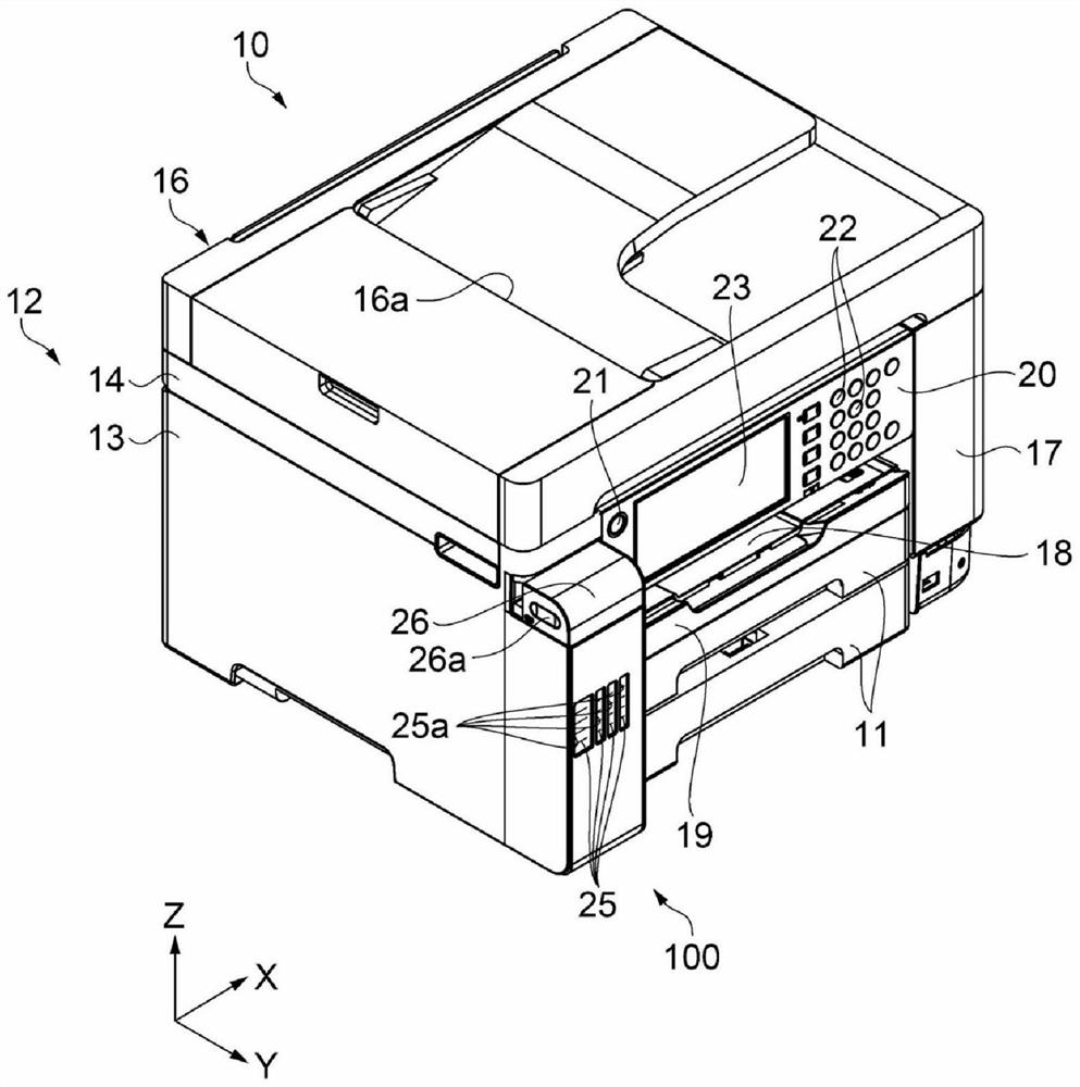
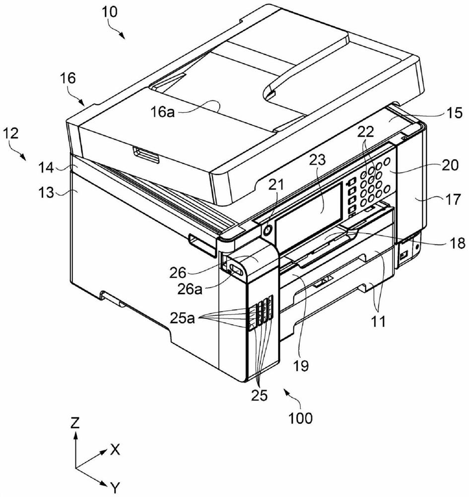
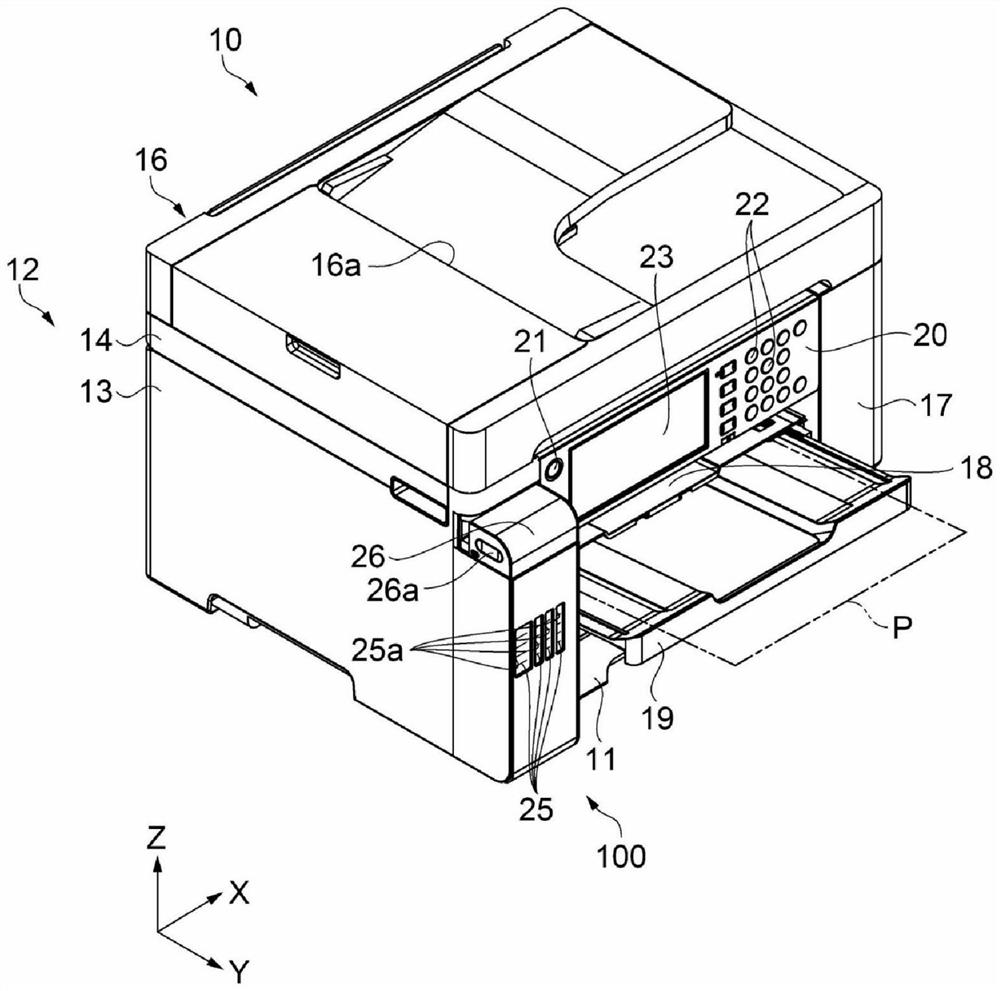
[0031] First, the configuration of the printer 10 will be described.
[0032] Figure 1 to Figure 4 It is a perspective view showing the structure of the printer 10 . in particular, figure 1 represents the appearance of the printer 10, figure 2 Indicates the open state of the cover portion 16 serving as the cover unit in the printer 10, image 3 represents the discharge state of the medium P in the printer 10, Figure 4 The open state of the tank cover 26 in the printer 10 is shown.
[0033] like figure 1 As shown, the printer 10 is an ink jet printer that ejects ink, which is an example of a liquid, on a medium P such as paper to perform recording.
[0034] In addition, in figure 1 , the X-axis, Y-axis and Z-axis which are orthogonal to each other are drawn. figure 1 The X-axis, Y-axis, and Z-axis of the graph correspond to the X-axis, Y-axis, and Z-axis of other graphs. The graphs shown hereafter also have an X-axis, a Y-axis, and a Z-axis added as necessary. Th...
no. 2 approach
[0090] Next, the second embodiment will be described. In the present embodiment, a configuration different from that of the first embodiment, that is, the configuration of the ink tank unit 100A will be described. In addition, since the structure other than the ink tank unit 100A is the same as the structure of 1st Embodiment, description is abbreviate|omitted.
[0091] Figure 14 It is a cross-sectional view showing the structure of the ink tank unit 100A according to the present embodiment.
[0092] Here, in the above-mentioned first embodiment, as Figure 5 As shown, the first rotating shaft 37 and the second rotating shaft 38 are arranged on the +Y direction side rather than the ink inlet opening 49a, and the tank cover 26 and the cover member 50 are rotated to the +Y direction side to allow the ink inlet opening 49a open.
[0093] However, in the ink tank unit 100A of the present embodiment, as Figure 14 As shown, the second rotating shaft 38 for rotating the tank c...
PUM
Abstract
The present invention provides an ink tank unit that is convenient for a user to use. An ink tank unit in which ink supplied to an ink jet head is replenished from an ink replenishment container, the ink tank unit comprising: an ink tank capable of accommodating the ink; and an ink inlet conduit for supplying the ink tank to the ink tank the ink is introduced into the interior; a keyway member is attached to the ink tank and has a hole in which the ink inlet conduit is arranged, and a recess capable of engaging with a key provided in the ink replenishing container and a cover member provided with a cover for closing or opening an ink inlet opening of the ink inlet conduit, and the cover member rotates at least between a closed state and an open state of the cover around a first rotation axis , in a plan view, the axis of the first rotating shaft is arranged at a position overlapping with a region from one end of the recessed portion to the hole.
Description
technical field [0001] The present invention relates to an ink tank unit and a printer. Background technique [0002] Conventionally, there has been known an inkjet printer including: an image forming unit having a main tank; an image reading unit that reads an image of a document; and a replenishing unit provided with a replenishing port for replenishing ink to the main tank. (For example, refer to Patent Document 1). [0003] [Prior Art Literature] [0004] [Patent Literature] [0005] [Patent Document 1] Japanese Patent Laid-Open No. 2008-296508 [0006] In the above-described inkjet printer, when replenishing ink to the main tank, in order to expose the replenishment port, it is necessary to rotate the image reading unit. However, when replenishing ink, it is not easy for the user to understand the operation of opening the cover unit arranged on the upper part of the printer, such as the image reading unit (for example, the scanner unit), and the cover unit is relati...
Claims
Application Information
Patent Timeline
Application Date:The date an application was filed.
Publication Date:The date a patent or application was officially published.
First Publication Date:The earliest publication date of a patent with the same application number.
Issue Date:Publication date of the patent grant document.
PCT Entry Date:The Entry date of PCT National Phase.
Estimated Expiry Date:The statutory expiry date of a patent right according to the Patent Law, and it is the longest term of protection that the patent right can achieve without the termination of the patent right due to other reasons(Term extension factor has been taken into account ).
Invalid Date:Actual expiry date is based on effective date or publication date of legal transaction data of invalid patent.

