Apparatus and methods for handling materials in a 3-D printer

a 3-d printer and material handling technology, applied in the field of 3d printers, can solve the problems of affecting the operation of the printhead, no binder material being dispensed or inaccurately, powder handling and powder and dust management, etc., to achieve the effect of reducing the contamination of the printer and surrounding area from escaped or spilled powder, improving the efficiency of the 3d printing system, and reducing the amount of waste generated by the process

Active Publication Date: 2008-01-10
3D SYST INC
View PDF24 Cites 127 Cited by
  • Summary
  • Abstract
  • Description
  • Claims
  • Application Information

AI Technical Summary

Benefits of technology

[0007] The invention provides an apparatus for handling powder and other materials in a 3D printer and provides a means for automatically loading, applying, recovering, and filtering powder used in 3D printing. As a result, the efficiency of the 3D printing system can be improved, the waste generated by the process can be minimized, and contamination of the printer and surrounding area from escaped or spilled powder can be substantially reduced.
[0023] In various embodiments, each plenum segment includes a valve for connecting an associated filter portion to a vacuum source for drawing air carrying powder through the filter, the filter preventing the powder from passing therethrough. In addition, the valves can be adapted to connect the associated filter portion to a positive pressure. In one embodiment, the valves can be two-way, three-position type valves, such that a single valve assembly can be used to shift between vacuum and positive pressure in communication with the filter portion. In one embodiment, the filter portions are alternately exposed to the vacuum source and the positive pressure. Additionally, the filter portion can be alternately exposed to the vacuum source and the positive pressure sequentially. Further, the system can be adapted for mounting to an inlet of a powder dispensing hopper. The filter can be coated with an abrasion resistant material to reduce filter damage from exposure to the powder.
[0024] In another aspect, the invention relates to a multiport valve for use in a powder transfer system of a three-dimensional printer. The valve includes a first portion defining a port radially disposed a fixed distance from a central point and a second portion coupled to the first portion at the central point. The second portion is rotatable relative to the first portion and defines a plurality of ports. The plurality of ports are radially disposed about the central point from the same fixed distance as the port on the first portion, so that each port is alignable with the port in the first portion when the second portion is rotated to a set position, thereby enabling flow therebetween.
[0027] In various embodiments, the capping station includes a plurality of caps disposed on the carrier. The plurality of caps may be spaced to align with a plurality of printheads in a carriage. In one embodiment, the carrier includes a fixed support, a movable support, and an actuator tab for contacting at least one of the printhead and the printhead carriage. Forward movement of at least one of the printhead and the printhead carriage into contact with the actuator tab causes the movable support to pivot relative to the fixed support, thereby orienting the cap into a horizontal position relative to the printhead face. Continued movement of at least one of the printhead and the printhead carriage causes the cap to seal against the printhead face. Further, the capping station can include a stop adapted for preventing continued forward movement of the printhead once capped. In one embodiment, the printhead cap is made of a compliant material that can expand and contract in response to a change in pressure when capping the printhead face (e.g., an increase in pressure may occur when the cap interfaces with the printhead face), thereby obviating the need for a vent in the cap. In one embodiment, the capping station uses a four-bar linkage for moving the cap between the vertical position and the horizontal position.
[0030] In another aspect, the invention relates to an electrical connection system for printheads in a three-dimensional printer. The connection system includes a base plate for connecting the system to a signal source, the base plate comprising a plurality of solder pads disposed in a set pattern, a connector mounted to the base plate and adapted for providing a signal to a printhead, the connector defining a plurality of stepped through holes oriented in the connector to correspond with the solder pads, and a plurality of pogo pins selectively disposed within the stepped through holes of the connector, the pogo pins supplying signals to the printheads from the signal source. The signal can provide at least one of power and instructions to the printhead. In one embodiment, the system includes a seal disposed between the connector and the base plate to prevent ingress of contamination.

Problems solved by technology

Apparatus for carrying out 3D printing typically generate dust, which can detrimentally effect the operation of the printheads.
For example, the dust can clog the jet nozzles that dispense the binder material, which can result in no binder material being dispensed or the binder material being dispensed inaccurately.
Powder handling and powder and dust management are major problems in 3D printing.
This always causes a large dust cloud and often results in a lot of powder being spilled.
The printing process also stirs up a lot of dust by spreading powder and dumping it into an overflow container.
Once the part is printed, the unprinted powder must be removed from the build box in a process that is tedious and often very messy.
The overflow container must be emptied back into the feed piston and this also involves lifting a heavy container, pouring powder out of the container, and the generation of a dust cloud, and often, spilled powder.
Depowdering the part after it has been printed creates additional problems.
Because of cost, most users want to recycle the powder removed from the part.
Both of these processes are extremely messy and get powder on the user, the floor, and the machine, and create dust clouds.

Method used


Image

  • Apparatus and methods for handling materials in a 3-D printer
  • Apparatus and methods for handling materials in a 3-D printer
  • Apparatus and methods for handling materials in a 3-D printer

Examples


Embodiment Construction

[0064] The systems and components described herein can be used with various 3D printers and related apparatus, such as those disclosed in U.S. Pat. No. 5,902,441, U.S. Pat. No. 6,007,318, U.S. Patent Application No. 2002 / 0079601, U.S. Patent Application No. 2004 / 0012112, U.S. Patent Application No. 2004 / 0265413, U.S. Patent Application No. 2005 / 0280185, U.S. Patent Application No. 2006 / 0061613, and U.S. Patent Application No. 2006 / 0061318, the entire disclosures of which are hereby incorporated herein by reference.

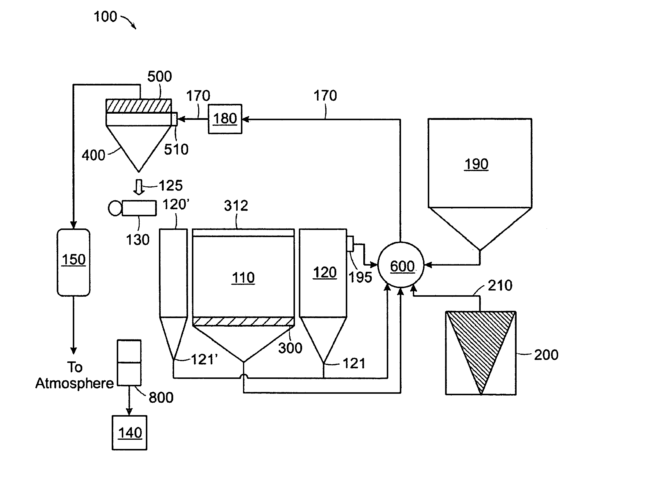
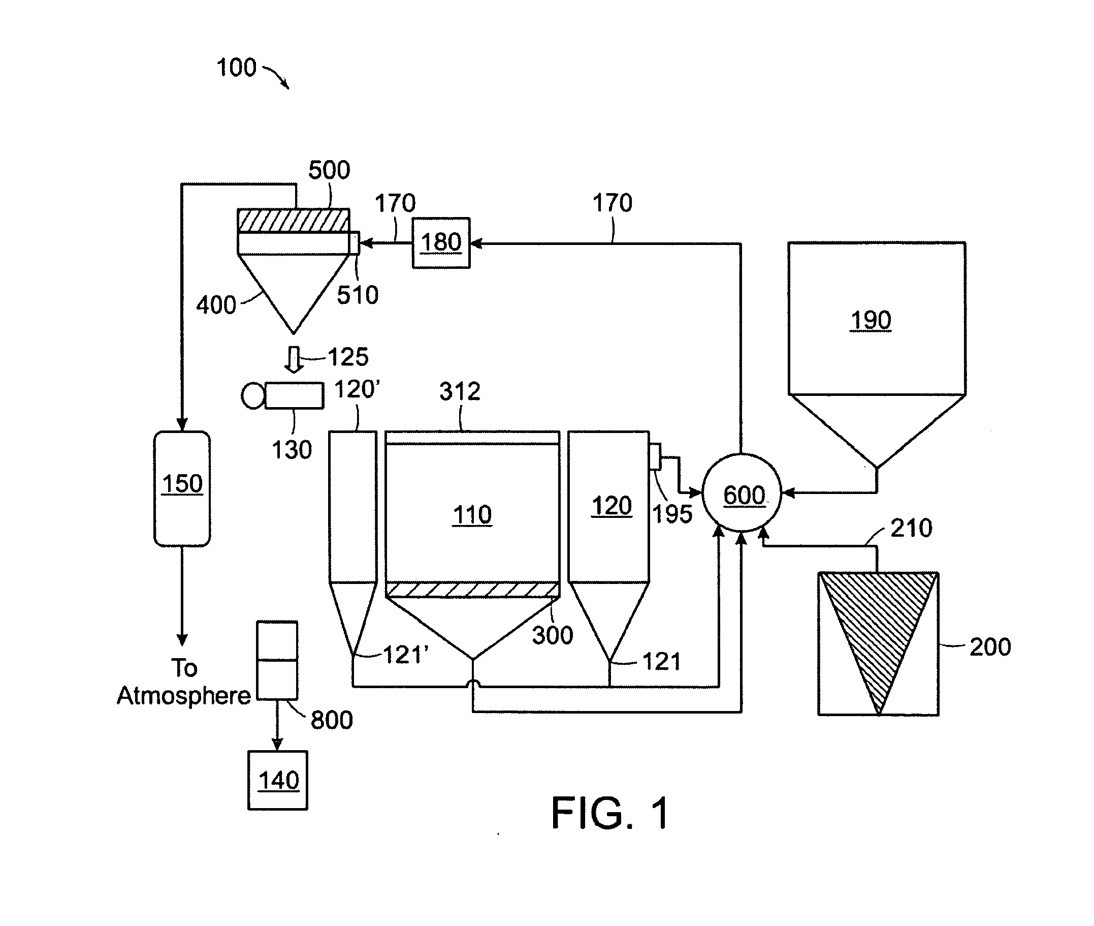
[0065] In one embodiment of the invention, a pneumatic means of handling powder is provided, allowing the powder to be transferred from one location to another within the 3D printer system automatically and quickly with minimal or substantially no loss of powder or contamination of the printer and / or surrounding environment. A schematic diagram showing elements of this configuration can be seen in FIG. 1.

[0066]FIG. 1 shows a powder handling system 100 for a 3D printer. T...


PUM

PropertyMeasurementUnit
interior volumeaaaaaaaaaa
volumeaaaaaaaaaa
movementaaaaaaaaaa

Abstract

The present invention is directed towards methods and apparatus for handling powder in a 3D printer. The invention includes a means of transporting powder from multiple sources to a powder dispensing apparatus with minimal user intervention, thus reducing contamination of the 3D printer and surrounding area with loose powder, while also providing a means of improving the recycling of powder for re-use.

Description

CROSS-REFERENCE TO RELATED APPLICATIONS [0001] This application claims the benefit of and priority to U.S. Provisional Patent Application Ser. No. 60 / 808,721, filed on May 26, 2006, the entire disclosure of which is hereby incorporated by reference herein. This application also incorporates herein by reference three U.S. patent applications filed of even date herewith and identified by Attorney Docket Nos. ZCO-116A, ZCO-116B, and ZCO-116C.FIELD OF THE INVENTION [0002] The present invention relates generally to the field of 3D printers and in particular to powder and waste handling systems therefor. BACKGROUND OF THE INVENTION [0003] Generally, 3D printing involves the use of an inkjet type printhead to deliver a liquid or colloidal binder material to layers of a powdered build material. The printing technique involves applying a layer of a powdered build material to a surface typically using a roller. After the build material is applied to the surface, the printhead delivers the liq...

Claims


Application Information

Patent Timeline
Patent Type & Authority Applications(United States)
IPC IPC(8): G03G21/10B41J2/165B65D83/06
CPCB29C31/02B29K2105/251B29C67/0096B29C67/0077B29C64/153B29C64/35Y10T137/86187B33Y30/00B33Y40/00B29C64/357B33Y40/20B29C67/00
Inventor DAVIDSON, THOMASHERNANDEZ, ANDRES T.VILLEGAS, ROBERT
Owner 3D SYST INC
Why Eureka
Try Eureka