

a security door
An anti-theft door and door panel technology is applied to anti-theft doors. It can solve the problems of receiving small express delivery, the danger of anti-theft doors, and the failure of anti-theft doors to achieve the effect of high safety performance.
- Summary
- Abstract
- Description
- Claims
- Application Information
AI Technical Summary
Problems solved by technology
Method used
Image

Examples
Embodiment 1
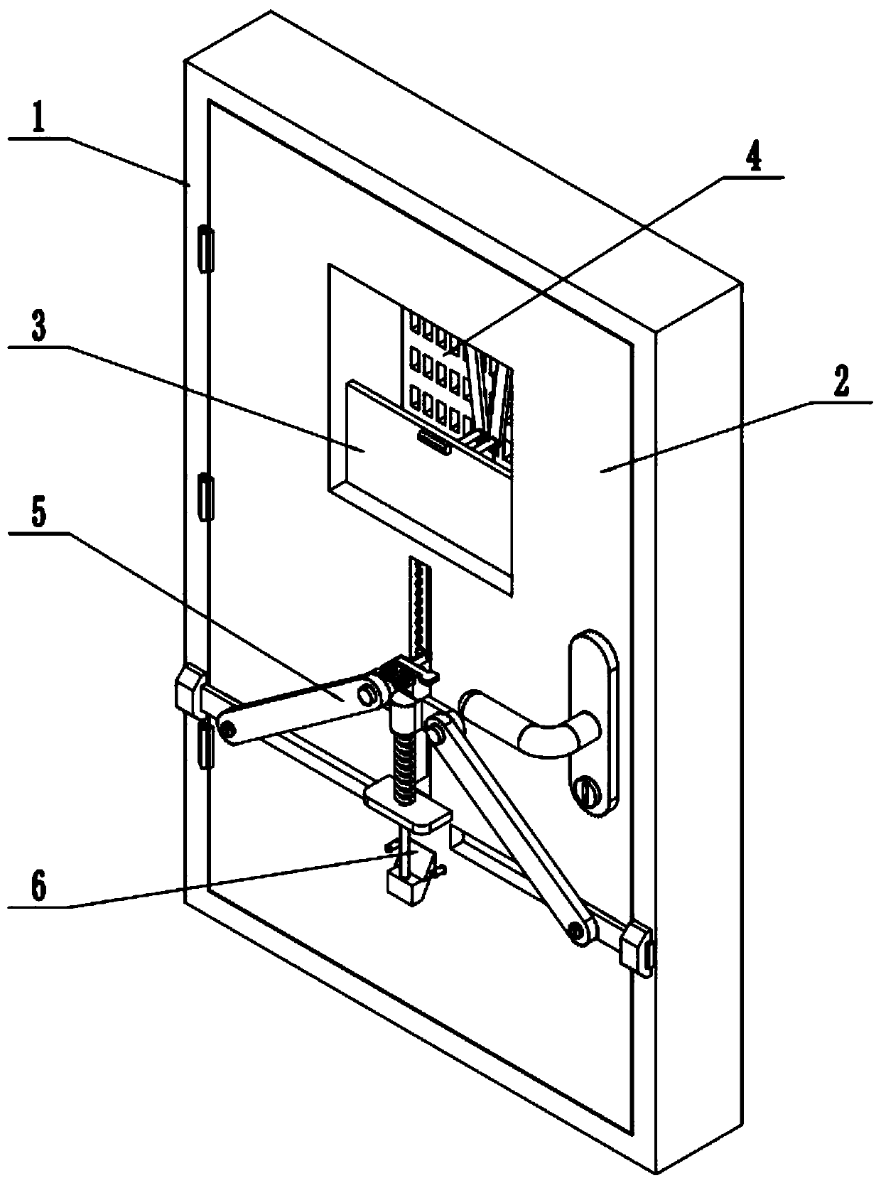
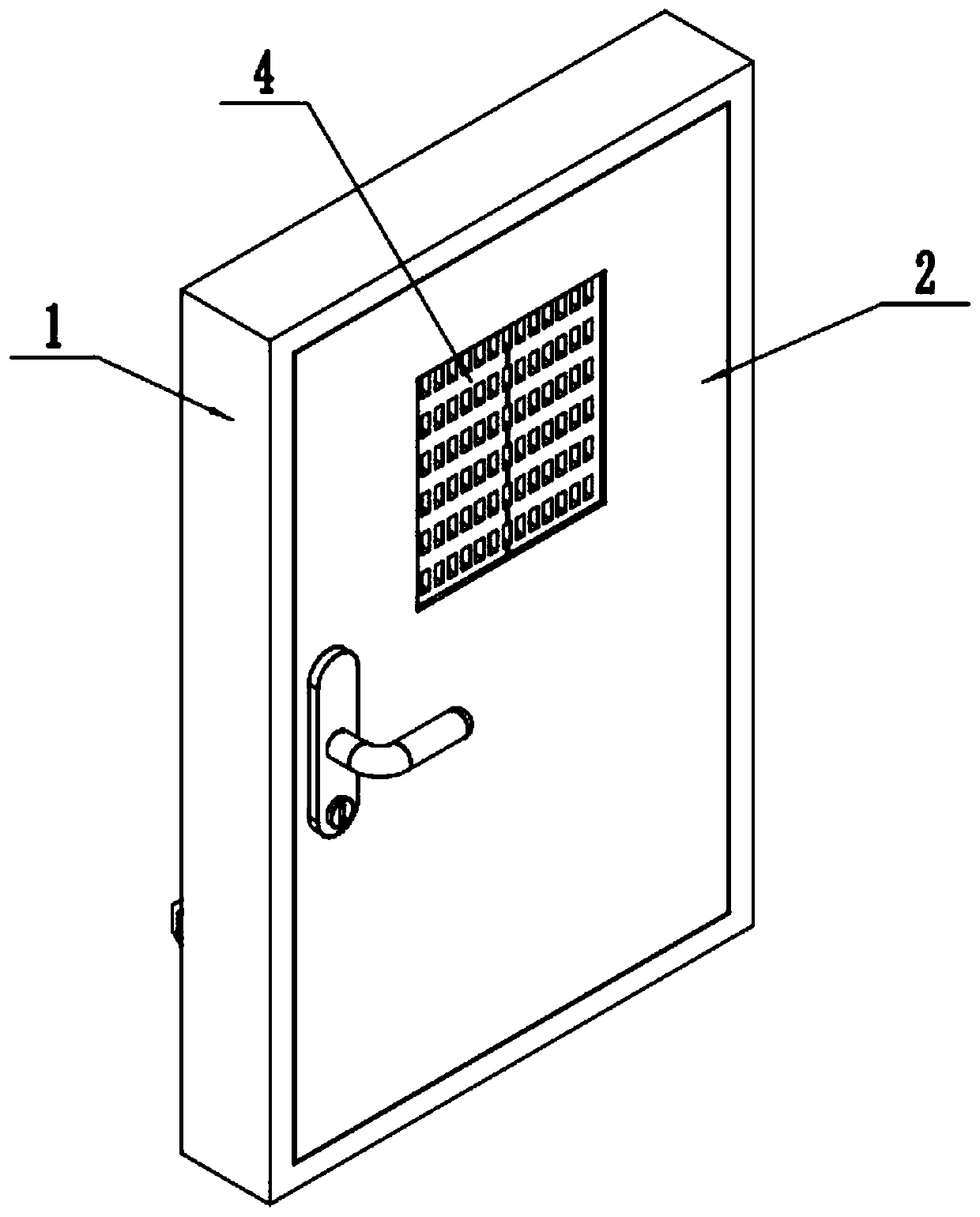
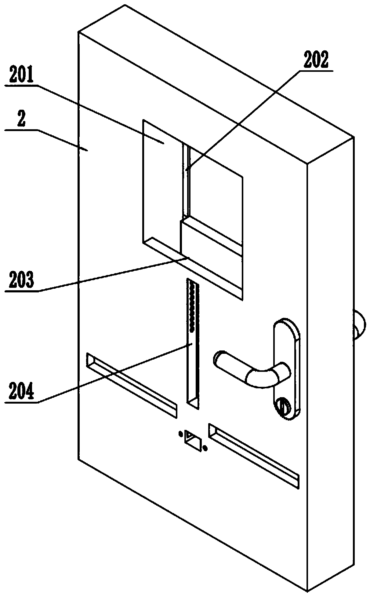
[0032] Such as Figure 1-12 As shown, a security door includes a door frame 1, a door body 2 with an anti-theft lock, a movable door panel 3, a ventilation door panel 4, a door inner lock 5 and a locking unlocker 6, and the door body 2 is rotatably connected to the door frame 1; the upper end of the door body 2 is provided with a door chute 201, the left and right sides of the front end of the door chute 201 are respectively provided with a transverse chute 202, and the lower side of the rear end of the door chute 201 is provided with a longitudinal chute 203, The middle part of the rear end of the longitudinal chute 203 is provided with a guide chute 204; the movable door panel 3 is slidably fitted in the door panel chute 201, the longitudinal chute 203 and the guide chute 204; the front end of the movable door panel 3 is connected to the ventilation door panel 4 The ventilation door panel 4 is slidably fitted in the door panel chute 201 and the two transverse chute 202; the ...
Embodiment 2
[0034] Such as Figure 1-12As shown, the movable door panel 3 includes an inner door panel 301, a push seat 302, a transverse guide plate 303, a sliding plate 304, a control panel 305, an insertion rod 306, a tension spring 307 and a compression spring 308; the inner door panel 301 is slidably fitted on the door panel in the chute 201 and the longitudinal chute 203; the lower end of the rear side of the inner door panel 301 is fixedly connected to the push seat 302; the push seat 302 is slidably fitted in the guide chute 204; Guide plate 303; the rear end of the sliding plate 304 is slidably fitted in the middle part of the transverse guide plate 303; the front end of the sliding plate 304 is fixedly connected to the insertion rod 306; the left and right ends of the sliding plate 304 are respectively fixedly connected to the right end of the extension spring 307 and the left end of the compression spring 308; the left end of the extension spring 307 and the right end of the co...
Embodiment 3
[0036] Such as Figure 1-12 As shown, the ventilation door panel 4 includes an outer door panel 401, a push-pull panel 402 and a push-pull seat 403; the outer door panel 401 is provided with two, and the two outer door panels 401 are symmetrically slidably fitted in the door panel chute 201 and the two transverse chute 202; the push-pull plate 402 is provided with two, the upper ends of the two push-pull plates 402 are respectively rotated and connected to the upper ends of the rear sides of the two outer door panels 401, and the lower ends of the two push-pull plates 402 are respectively rotated and fitted on the two sides of the push-pull seat 403. end; the push-pull seat 403 is fixed on the upper end of the front side of the inner door panel 301 . When the inner door panel 301 is opened downward, it can drive the push-pull seat 403 to move downward. When the push-pull seat 403 moves downward, it can drive the angle between the two push-pull plates 402 to become smaller, and...
PUM
 Abstract
Description
Claims
Application Information