Reconfigurable optical coherence tomography (oct) system

A technology of optical coherence tomography and imaging, applied in the direction of optical devices, diagnosis, laser surgery, etc., to achieve the effect of optimizing performance

Inactive Publication Date: 2019-12-17
ALCON INC
View PDF8 Cites 0 Cited by
  • Summary
  • Abstract
  • Description
  • Claims
  • Application Information

AI Technical Summary

Problems solved by technology

[0005] However, even with these recent advances, the functionality and performance of biometric and imaging instruments require further substantial improvement and development

Method used


Image

  • Reconfigurable optical coherence tomography (oct) system
  • Reconfigurable optical coherence tomography (oct) system
  • Reconfigurable optical coherence tomography (oct) system

Examples


Embodiment Construction

[0018] In the following description, specific details are set forth in order to describe certain embodiments. It will be apparent, however, to one skilled in the art that the disclosed embodiments may be practiced without some or all of these specific details. The specific examples presented are intended to be illustrative, not restrictive. Those skilled in the art will recognize that other materials, although not explicitly described herein, are within the scope and spirit of the disclosure.

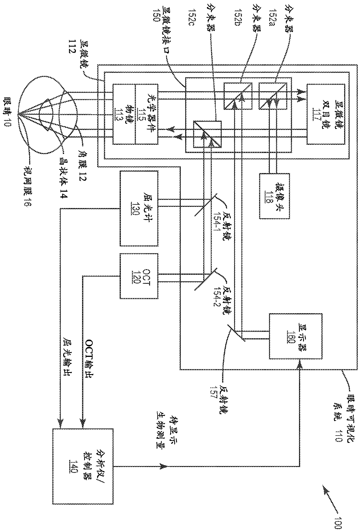
[0019] Embodiments of the techniques and devices of the present disclosure may be employed in both microscope-mounted and microscope-integrated optical coherence tomography (OCT) systems. figure 1 An example of an OCT system 100 integrated with a microscope is shown and is presented to demonstrate the basic principles of OCT.

[0020] System 100 includes an eye visualization system 110 configured to provide a visual image of an imaged region of eye 10, an optical coherence tomography ...


PUM


Abstract

An optical coherence tomography (OCT) apparatus comprising a light source module including two or more selectable light sources or one light source configured to selectively operate in two or more source operating modes , or a combination of both, and further comprising an OCT engine coupled to the light source module, the OCT engine comprising an OCT interferometer. The OCT apparatus further includes a mode-switching optics module coupled to the OCT engine and including one or more interchangeable, selectable, or adjustable optics such that the mode-switching The optics module is configured to selectively provide two or more optical configurations of the optical path between the OCT engine and the imaged object according to two or more corresponding modes of operation.

Description

technical field [0001] Embodiments disclosed herein relate to devices, systems, and methods for adjusting optical performance characteristics in optical coherence tomography (OCT) systems. Background technique [0002] Current ophthalmic refractive surgery methods, such as cataract surgery, endokeratomileusis, laser in situ keratomileusis (LASIK), and photorefractive keratectomy (PRK), rely on ocular biometric data to prescribe optimal Refractive correction prescription. Historically, ophthalmic surgery has used ultrasound biometric instruments to image parts of the eye. In some cases, these biometric instruments produce a so-called A-scan of the eye: acoustic echo signals from all interfaces along the imaging axis (typically aligned with the optical axis of the eye): parallel to it, or only at a small angle. Other instruments produce so-called B-scans, essentially assembling a collection of a-scans taken successively as the head or tip of the biometric instrument scans al...

Claims


Application Information

Patent Timeline
Patent Type & Authority Applications(China)
IPC IPC(8): A61B3/10
CPCA61B3/102A61B3/13A61B5/0066A61F9/008A61F2009/00851G01B9/02091
Inventor C·本德尔M·帕帕克俞凌峰
Owner ALCON INC
Why Eureka
Try Eureka