Fiber tow treatment device and method

A fiber tow and processing device technology, which is applied in the field of fiber tow processing devices, can solve the problems of fiber damage and poor stability, achieve stable fiber spreading, and reduce the effect of turbulent flow on the tow

Active Publication Date: 2019-12-20
SHANXI INST OF COAL CHEM CHINESE ACAD OF SCI
View PDF10 Cites 0 Cited by
  • Summary
  • Abstract
  • Description
  • Claims
  • Application Information

AI Technical Summary

Problems solved by technology

[0003] Aiming at the problems of poor stability and serious damage to fibers during the expansion process of the fiber tow, the present invention provides a device and method for realizing the expansion of the fiber tow through a stable airflow

Method used


Image

  • Fiber tow treatment device and method
  • Fiber tow treatment device and method
  • Fiber tow treatment device and method

Examples


Embodiment 1

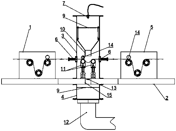
[0034] Such as Figure 1 to Figure 3 As shown, a fiber tow spreading device includes a front drawer 1, a mounting frame 2, an upper cavity 3, a lower cavity 4 and a rear drawer 5, the front drawer 1, the upper cavity 3 and the rear The tractor 5 is arranged on the upper surface of the mounting frame 2 successively from left to right, and the fiber inlet / outlet ports of the front tractor 1, the upper cavity 3 and the rear tractor 5 are located on the same horizontal straight line, and the lower cavity 4 is arranged on the lower surface of the mounting frame 2, and corresponds to the position of the upper cavity 3, the mounting frame 2 is provided with an airflow guide hole 15 passing through the upper cavity 3 and the lower cavity 4, and the airflow The guide hole 15 is located in the middle of the cavity, and an anemometer 13 is arranged in the air flow guide hole 15 for measuring the wind speed passing through the air flow guide hole 15. Fiber outlets are provided with a lab...

Embodiment 2

[0040] Such as Figure 1 to Figure 3 As shown, a processing device for fiber tow includes a front drawer 1, a mounting frame 2, an upper cavity 3, a lower cavity 4 and a rear drawer 5, and the front drawer 1, the upper cavity 3 and the rear The tractor 5 is arranged on the upper surface of the mounting frame 2 successively from left to right, and the fiber inlet / outlet ports of the front tractor 1, the upper cavity 3 and the rear tractor 5 are located on the same horizontal straight line, and the front traction Press roller 14 is arranged above the drafting rollers of machine 1 and rear traction machine 5, and described press roller 14 is a rubber roller, which can play the role of increasing drafting force and positioning tow. The friction force on the tow can be increased by the rubber roller, so as to ensure the stability of the tow when it travels. The lower cavity 4 is arranged on the lower surface of the mounting frame 2, and corresponds to the position of the upper cav...

Embodiment 3

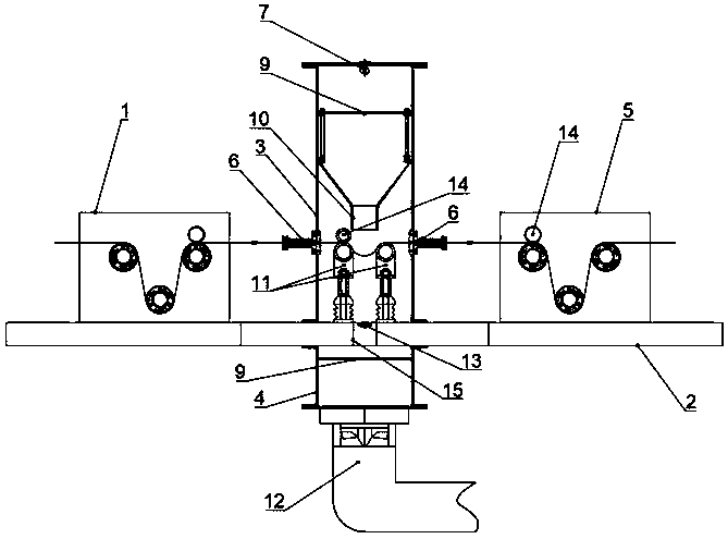
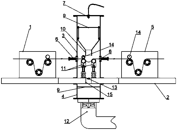
[0046] Such as figure 2 , Figure 4 , Figure 5 As shown, a processing device for fiber tow includes a front drawer 1, a mounting frame 2, an upper cavity 3, a lower cavity 4 and a rear drawer 5, and the front drawer 1, the upper cavity 3 and the rear The tractor 5 is arranged on the upper surface of the mounting frame 2 successively from left to right, and the fiber inlet / outlet ports of the front tractor 1, the upper cavity 3 and the rear tractor 5 are located on the same horizontal straight line, and the front traction Press roller 14 is arranged above the drafting rollers of machine 1 and rear traction machine 5, and described press roller 14 is a rubber roller, which can play the role of increasing drafting force and positioning tow. The friction force on the tow can be increased by the rubber roller, so as to ensure the stability of the tow when it travels. The lower cavity 4 is arranged on the lower surface of the mounting frame 2, and corresponds to the position of...


PUM


Abstract

The invention belongs to the technical field of fiber tow treatment and particularly relates to a fiber tow treatment device and method. The fiber tow treatment device comprises a front traction machine, a mounting rack, an upper cavity, a lower cavity and a rear traction machine, wherein the front traction machine, the upper cavity and the rear traction machine are sequentially arranged on the upper surface of the mounting rack from left to right, fiber inlets / outlets of the front traction machine, the upper cavity and the rear traction machine are located on the same horizontal straight line, and pressing rollers are arranged above drafting rollers of the front traction machine and the rear traction machine. By adopting the fiber tow treatment device and the fiber tow treatment method, the problems of poor stability and poor adjustability of fiber tows when the fiber tows advance in the existing air fiber spreading process are solved, and the fiber spreading atmosphere of the fiber tow treatment device can be uniformly distributed and concentrated in an effective area, so that the influence of turbulent flow on the tows is effectively reduced, the tow dispersing effect is improved, and adverse variables in an adjusting process are decreased.

Description

technical field [0001] The invention belongs to the technical field of fiber tow processing, and in particular relates to a processing device and method for fiber tow. Background technique [0002] In the process of fiber application, it is usually necessary to make the fiber tow as thin as possible in the unfolded state, that is, fiber spreading treatment. At present, there are two main methods of spreading fibers in common use. One method is to use mechanical means to spread fibers, see Chinese patent (CN201520104863; CN201821646155); another method is to use air to spread fibers, see Chinese patent (CN201480072709). An airflow facing or at an angle to the fiber is added between the drafting rollers, and the high-speed airflow is used to realize the expansion of the fiber tow. The above two methods have obvious defects. The mechanical fiber spreading method will inevitably cause damage to the fiber, while in the air fiber spreading method, due to the unstable air flow, t...

Claims


Application Information

Patent Timeline
IPC IPC(8): D02J1/18
CPCD02J1/18
Inventor 吴刚平李文君刘玉婷
Owner SHANXI INST OF COAL CHEM CHINESE ACAD OF SCI
Why Eureka
Try Eureka