
Mark position detecting apparatus, drawing apparatus and mark position detecting method

A technology of marking position and detecting device, which is applied in the field of drawing devices, can solve the problems of lowering detection accuracy of the marking position, enlargement of the photographing part, high price of the photographing part, etc., and achieves the effect of reducing detection errors.

Active Publication Date: 2019-12-31
DAINIPPON SCREEN MTG CO LTD
View PDF18 Cites 2 Cited by
  • Summary
  • Abstract
  • Description
  • Claims
  • Application Information

AI Technical Summary

Problems solved by technology

In this case, the resolution of the image is lowered, and the detection accuracy of the position of the mark is lowered.
In order to maintain the resolution, it is necessary to increase the number of pixels of the imaging sensor, but in this case, the imaging unit becomes expensive and the imaging unit becomes physically larger

Method used


Image

  • Mark position detecting apparatus, drawing apparatus and mark position detecting method
  • Mark position detecting apparatus, drawing apparatus and mark position detecting method
  • Mark position detecting apparatus, drawing apparatus and mark position detecting method

Examples


Embodiment Construction

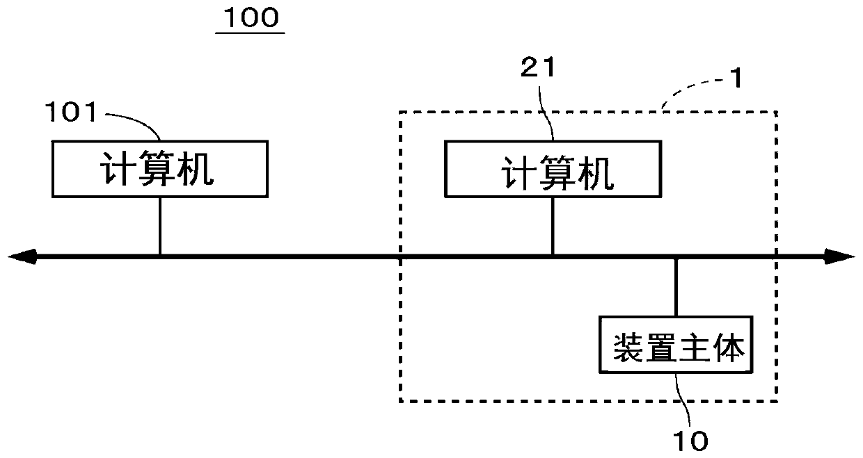
[0047] figure 1 It is a block diagram showing the configuration of the rendering system 100 according to one embodiment of the present invention. The drawing system 100 is a system that irradiates light onto a photosensitive material on a substrate such as a printed wiring board to draw a pattern such as wiring on the photosensitive material. Preferably, the substrate is a flexible printed wiring substrate. As the substrate, various other substrates can be used, and it may be a rigid substrate or a substrate other than wiring for circuits.

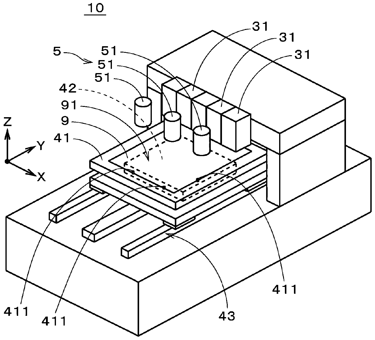
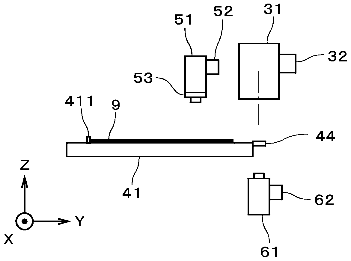
[0048] The rendering system 100 has a computer 101 and a rendering device 1 . The drawing device 1 includes a function as a mark position detection device that detects the position of a mark on the substrate. The computer 101 is used to generate design data representing the overall pattern to be drawn on the substrate. Design data is, for example, vector data representing an overall pattern. The drawing device 1 has a computer 21 and ...


PUM


Abstract

A drawing apparatus of the present invention includes a function of a mark position detecting apparatus for detecting a position of a mark on a substrate held by a workbench. The drawing apparatus acquires a first image (83a) representing a first region including a position on a design of a mark on a substrate and two second images (83b) representing a second region that only partially overlaps the first region while the workbench is moving. The first image (83a) and the second images (83b) are synthesized to generate a synthesized image (85). The drawing apparatus finds the position of the marker on the basis of the synthesized image (85). As a result, it is possible to easily expand the field of view without reducing the resolution of an imaging unit, and to reduce detection errors in the position of the mark on the substrate.

Description

technical field [0001] The present invention relates to a technique for detecting the position of a mark on a substrate, preferably a drawing device for drawing a pattern on a substrate. Background technique [0002] Conventionally, drawing devices that irradiate light onto a substrate to directly draw a pattern on the substrate have been used in various situations. Such a rendering method is also called direct imaging. Before drawing, the position of a mark called an alignment mark formed on the substrate is read by an imaging unit, and the amount of deviation between the position of the mark and the position on design is obtained. Then, the position, expansion and contraction amount, strain amount, etc. of the substrate are obtained based on the offset amount, and drawing is performed while modifying the drawing data in real time with reference to these information. Accordingly, it is possible to achieve highly accurate drawing in accordance with the positional displacem...

Claims


Application Information

Patent Timeline
Patent Type & Authority Applications(China)
IPC IPC(8): G01B11/00G03F9/00
CPCG01B11/00G03F9/7088G03F7/70683G03F9/7084G03F7/70775G03F7/706851G03F7/706835G03F9/7019G03F7/70725
Inventor 田中尚武
Owner DAINIPPON SCREEN MTG CO LTD
Learn More