
Display device

A technology for display devices and display areas, which is applied in the direction of identification devices, diodes, instruments, etc., and can solve problems such as affecting the camera to take pictures

Pending Publication Date: 2019-12-31
KUNSHAN GO VISIONOX OPTO ELECTRONICS CO LTD
View PDF11 Cites 8 Cited by
  • Summary
  • Abstract
  • Description
  • Claims
  • Application Information

AI Technical Summary

Problems solved by technology

[0003] Based on this, it is necessary to provide a display device for the problem of digging holes in the display area and affecting the camera to take pictures.

Method used


Image

  • Display device
  • Display device
  • Display device

Examples


Embodiment Construction

[0027] In order to make the above objects, features and advantages of the present invention more comprehensible, specific implementations of the present invention will be described in detail below in conjunction with the accompanying drawings. In the following description, numerous specific details are set forth in order to provide a thorough understanding of the present invention. However, the present invention can be implemented in many other ways different from those described here, and those skilled in the art can make similar improvements without departing from the connotation of the present invention, so the present invention is not limited by the specific embodiments disclosed below.

[0028] It should be noted that when an element is referred to as being “disposed on” another element, it may be directly on the other element or there may also be an intervening element. When an element is referred to as being "connected to" another element, it can be directly connected t...


PUM


Abstract

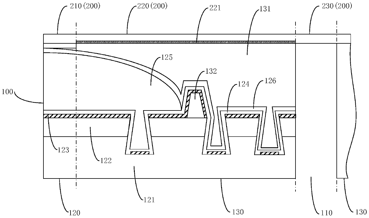
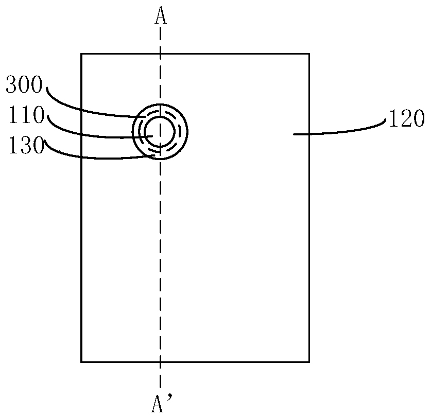
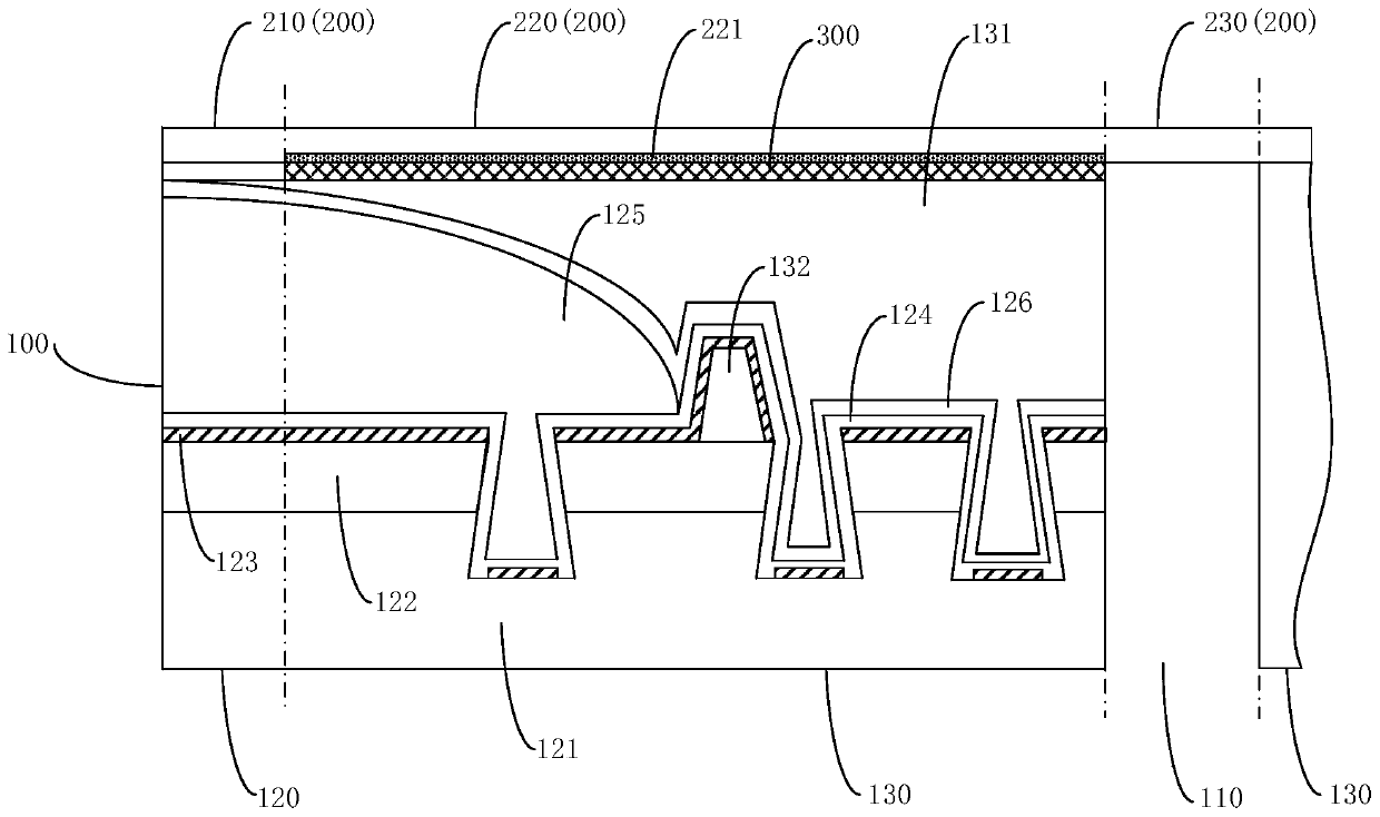
The invention relates to a display device, wherein the display device comprises a display panel and a cover plate covering the display panel; the display panel is provided with a through hole penetrating through the thickness direction of the display panel, the display panel further comprises a display area and a frame area, the display area surrounds the frame area, and the frame area surrounds the through hole; the cover plate comprises a first area, a second area and a third area, the first area covers the display area, the second area covers the frame area, and the third area covers the through hole, wherein the surface, close to the display panel, of the second area is provided with a shading part. The cover plate is divided into the first area, the second area and the third area by the display device, the shading part is arranged on the surface, close to the display panel, of the second area of the cover plate, that is, the shading part is arranged around the through hole, a light ray transmission path is changed or the light rays emitted from the display area are absorbed by using the shading part, the light rays are prevented or reduced from being emitted from the through hole, the photosensitive effect of a camera shooting module can be improved, and the display effect of the display device can also be improved.

Description

technical field [0001] The invention relates to the display field, in particular to a display device. Background technique [0002] With the advancement of display technology, displays with a high screen-to-body ratio are becoming more and more popular. Usually, the camera of the display device is set in the non-display area of ​​the display screen, and in order to increase the screen ratio of the display screen, a method is proposed to dig a hole in the display area and install equipment such as a camera or an earpiece in the hollow of the display area area, thereby canceling the non-display area of ​​the frame of the display device. However, digging holes in the display area may easily lead to side leakage of light from the organic light-emitting layer, affecting the camera to take pictures, and also affecting the display effect. Contents of the invention [0003] Based on this, it is necessary to provide a display device for the problem that digging a hole in the disp...

Claims


Application Information

Patent Timeline
IPC IPC(8): G09F9/30
CPCG09F9/30H10K59/879H10K59/65H10K59/871H10K59/873H10K59/877H10K59/878H10K59/126H10K59/121
Inventor 刘明星赵栋陈月涛甘帅燕李伟丽冯士振
Owner KUNSHAN GO VISIONOX OPTO ELECTRONICS CO LTD
Learn More