A microbial fuel cell, application and pipeline gas monitoring device
What is AI technical title?
AI technical title is built by Patsnap AI team. It summarizes the technical point description of the patent document.
A technology of fuel cells and microorganisms, applied in biochemical fuel cells, measuring devices, electrical components, etc., can solve the problems of unstable battery voltage and low efficiency of wastewater treatment, and achieve the effect of saving energy
Active Publication Date: 2020-11-03
XI'AN UNIVERSITY OF ARCHITECTURE AND TECHNOLOGY
View PDF13 Cites 0 Cited by
Summary
Abstract
Description
Claims
Application Information
AI Technical Summary
This helps you quickly interpret patents by identifying the three key elements:
Problems solved by technology
Method used
Benefits of technology
Problems solved by technology
[0004] In view of the above-mentioned deficiencies and defects of the prior art, the purpose of the present invention is to provide a microbial fuel cell, application and pipeline gas monitoring device to solve the problem of unstable voltage of the microbial fuel cell and low wastewater treatment efficiency in the prior art. question
Method used
Image
Click on the blue label to locate the original text in one second.
Reading with bidirectional positioning of images and text.
Examples
Embodiment 1
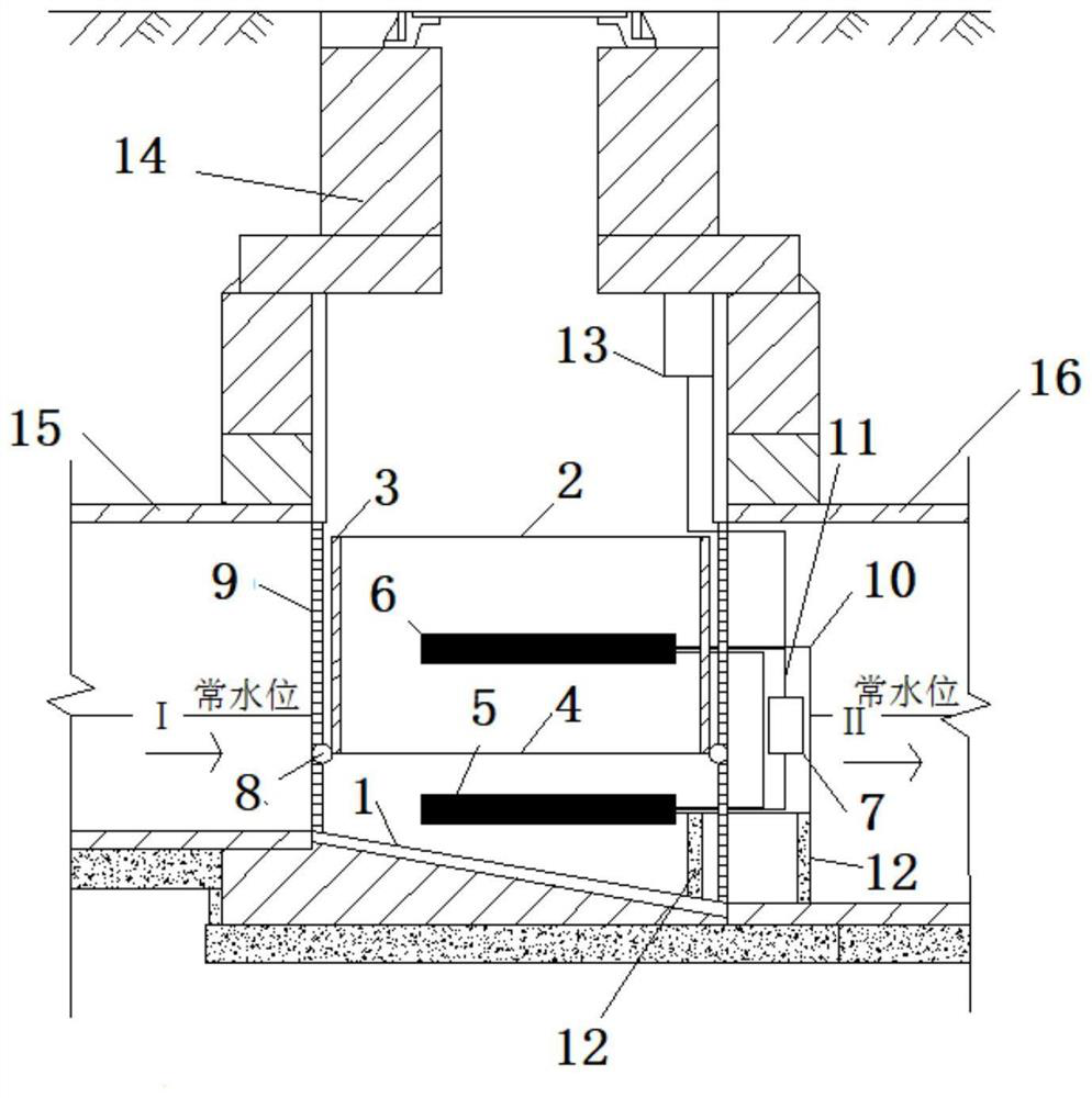
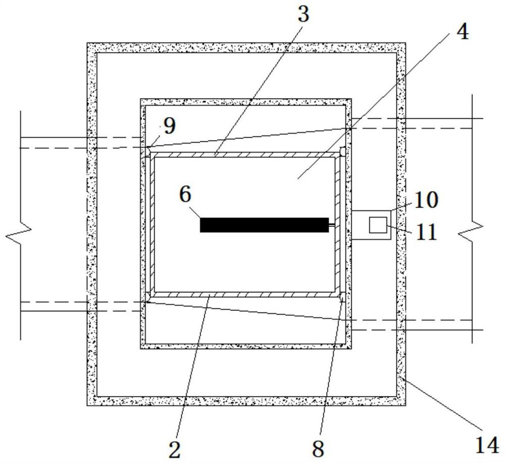
[0025] A microbial fuel cell, comprising an anode chamber 1 and a cathode chamber 2 connected to the anode chamber 1, the cathode chamber 2 is surrounded by baffles 3, and the bottom is an ion exchange membrane 4, the anode chamber 1 and the cathode chamber 2 An anode 5 and a cathode 6 are respectively arranged inside, one end of the anode 5 and the cathode 6 is connected through an external circuit 7, the outside of the anode 5 is coated with a biofilm, and the ion exchange membrane 4 is connected to a floating ball 8 , the floating ball 8 is placed in the guide rail 9, and the guide rail 9 is vertically fixed in the anode chamber 1.
[0026] In this embodiment, four floating balls are arranged at the four corners of the ion exchange membrane, and four guide rails are arranged correspondingly.
[0027] The ion-exchange membrane 4 and the cathode chamber 2 fixed thereon can slide up and down in the guide rail through the floating ball, so that the ion-exchange membrane 4 is in...
Embodiment 2
[0040] A pipeline gas monitoring device includes a gas detector 13 and the microbial fuel cell, and the gas detector 13 is connected to the energy storage battery 10 in the microbial fuel cell. It is used to monitor the hazardous gas in the pipeline, and alarm in time when the dangerous gas exceeds the normal index.
[0041] When the pipeline gas monitoring device is in use, put it into the inspection well 14, the gas detector 13 is fixed on the well wall, the support column 12 fixes the sealing box 9 in the inspection well 14, the guide rail 6 is fixed in the inspection well 14, and the sewage passes through The water inlet 15 enters from one side of the pipeline gas monitoring device, and flows out through the water outlet 16 from the other side.
[0042] The principle of this embodiment is as follows:
[0043] 1: Sewage enters the inspection well, enters from the water inlet, and contacts the anode electrode. The ion exchange membrane floats on the water surface with the wat...
PUM
Abstract
The invention discloses a microbial fuel cell, which comprises an anode chamber and a cathode chamber connected with the anode chamber, the cathode chamber is surrounded by baffles, and the bottom is an ion exchange membrane, and the anode chamber and the cathode chamber are respectively arranged with an anode and the cathode, one end of the anode and the cathode is connected through an external circuit, the outside of the anode is coated with a biofilm, the ion exchange membrane is connected to a floating ball, and the floating ball is placed in the guide rail, the The guide rails are fixed vertically in the anode chamber. The microbial fuel cell of the present invention uses the anaerobic microorganisms in the anode chamber of the battery to directly convert the chemical energy stored in the waste water organic matter into electrical energy, and connects the energy storage device to the external circuit of the microbial fuel cell to collect electrical energy and save electrical energy.
Description
technical field [0001] The invention belongs to the technical field of environmental protection and relates to pipeline environment treatment, in particular to a microbial fuel cell, its application and a pipeline gas monitoring device. Background technique [0002] Due to the depletion of fossil fuels and the generation of large amounts of wastewater due to rapid industrial development, there is an urgent need to adopt environmentally friendly and sustainable alternative energy technologies. Microbial fuel cells (MFCs) are considered as a promising technology in wastewater treatment due to their power generation capabilities and wastewater purification. Generally, an MFC has an anode chamber and a cathode chamber respectively, and a cation exchange membrane (CEM) is installed to separate the two chambers. In a microbial fuel cell wastewater is injected into the anode and the microbial community remains in the anode compartment. Microbes use the organic matrix as fuel to g...
Claims
Application Information
Patent Timeline
Application Date:The date an application was filed.
Publication Date:The date a patent or application was officially published.
First Publication Date:The earliest publication date of a patent with the same application number.
Issue Date:Publication date of the patent grant document.
PCT Entry Date:The Entry date of PCT National Phase.
Estimated Expiry Date:The statutory expiry date of a patent right according to the Patent Law, and it is the longest term of protection that the patent right can achieve without the termination of the patent right due to other reasons(Term extension factor has been taken into account ).
Invalid Date:Actual expiry date is based on effective date or publication date of legal transaction data of invalid patent.
Patent Type & AuthorityPatents(China)
IPC IPC(8): H01M8/16H01M4/86C02F3/00G01N33/00
CPCC02F3/005G01N33/0063H01M4/86H01M8/16Y02E60/50
Inventor卢金锁常娜张志强柴守宁
OwnerXI'AN UNIVERSITY OF ARCHITECTURE AND TECHNOLOGY

