Warning device for road traffic

A warning device, a technology for road traffic, applied in the directions of roads, roads, road signs, etc., can solve the problems of poor use of mirrors, misleading drivers, etc., and achieve the effect of improving clarity

Active Publication Date: 2020-01-10
HENAN UNIV OF URBAN CONSTR
View PDF5 Cites 15 Cited by
  • Summary
  • Abstract
  • Description
  • Claims
  • Application Information

AI Technical Summary

Problems solved by technology

[0002] In the prior art, a road reflector is usually installed at the corner of the road. The road reflector is also called a wide-angle mirror, a convex mirror, and a turning mirror. It is mainly used in various curves and intersections, which can expand the driver's field of vision and detect vehicles on the opposite side of the curve early. And pedestrians, in order to

Method used


Image

  • Warning device for road traffic
  • Warning device for road traffic
  • Warning device for road traffic

Examples


Embodiment 1

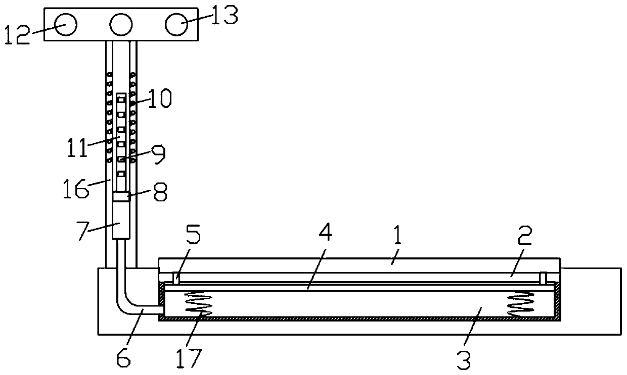
[0022] refer to figure 1 , a warning device for road traffic, including a strip groove 2 arranged on both sides of the road surface corner and a vertical pole 16 fixed on the roadside, a strip casing 3 with an opening at the upper end is installed in the strip groove 2, the strip A movable plate 4 is sealed and slidably connected in the shaped housing 3, and the lower end of the movable plate 4 is elastically connected to the inner bottom of the strip groove 2 through a spring 17. The upper end of the movable plate 4 is fixedly connected with a deceleration belt 1 through a support rod 5, and The upper end of 16 is provided with a chute 7 through which a sliding plug 8 is sealed and slidingly connected. The inner wall of 7 is embedded with helical coil 10, and the upper end of vertical rod 16 is equipped with warning plate 13, and warning light 12 is installed on the warning plate 13, and warning light 12 is coupled and connected to the two ends of helical coil 10, the lower e...

Embodiment 2

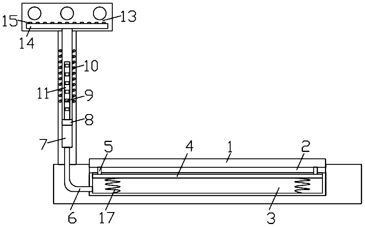
[0026] refer to Figure 2-3 , the side wall of the warning plate 13 is provided with an air chamber 14 communicating with the upper end of the chute 7, and the surface of the warning plate 13 is provided with an air jet hole 15, the air jet hole 15 is inclined towards the warning light 12, and the air jet hole 12 is inclined towards the warning light 12. 15, it is easier to remove the dust on the warning light 12.

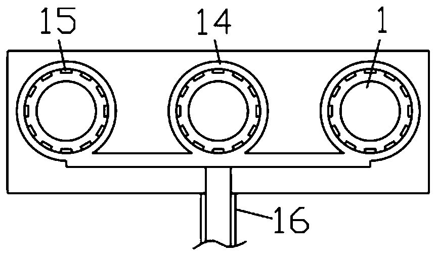
[0027] Furthermore, the air cavity 14 is arranged in a circular shape along the circumference of the warning light 12, and the air injection holes 15 are arranged at equal intervals inside the air cavity 14, and the air injection holes 15 arranged in a ring can clean the warning light 12 more comprehensively Ash.

[0028] In this embodiment, when the sliding plug 8 moves up, the air at the upper end of the chute 7 is pressed into the air chamber 14, and the air entering the air chamber 14 is sprayed out through the air injection hole 15, and the dust on the warnin...


PUM


Abstract

The invention discloses a warning device for road traffic. The warning device for road traffic comprises a strip-shaped groove arranged at two sides of a road surface turning and a stand rod fixed onthe roadside, a strip-shaped shell with an opening in the upper end is arranged in the strip-shaped groove, a movable plate is hermetically and slidably connected in the strip-shaped shell, the lowerend of the movable plate is elastically connected in the inner bottom of the strip-shaped groove through a spring, the upper end of the movable plate is fixedly connected with a deceleration band through supporting rods, the upper end of the stand rod is provided with a sliding groove in a through mode, a sliding plug is hermetically and slidably connected in the sliding groove, and the upper endof the sliding plug is fixedly connected with a vertical rod. According to the warning device for road traffic, the principle that magnets cut a magnetic induction line is utilized to generate induction current, so that warning lights on the side wall of a warning plate emits light, meanwhile, the magnets arranged at the same distance enable the generated current to be constantly changed, then thesituation that the warning lights flash is caused, the warning effect is achieved on a driver, the driver is reminded that a vehicle comes at the turning, and the preparation for meeting the vehicleis made in advance.

Description

technical field [0001] The invention relates to the technical field of traffic equipment, in particular to a warning device for road traffic. Background technique [0002] In the prior art, a road reflector is usually installed at the corner of the road. The road reflector is also called a wide-angle mirror, a convex mirror, and a turning mirror. It is mainly used in various curves and intersections, which can expand the driver's field of vision and detect vehicles on the opposite side of the curve early. And pedestrians, in order to reduce the occurrence of traffic accidents, but the road reflector uses a convex mirror, the image shows that the object is smaller than the actual, often misleading the driver to judge the actual distance, and because the car will raise a large number of Dust, dust is easy to adhere to the surface of the road reflector, resulting in poor actual use of the reflector. Contents of the invention [0003] The purpose of the present invention is t...

Claims


Application Information

Patent Timeline
IPC IPC(8): E01F9/608E01F9/615E01F9/529B08B5/02
CPCB08B5/02E01F9/529E01F9/608E01F9/615
Inventor 万祥云田好敏赵文君
Owner HENAN UNIV OF URBAN CONSTR
Why Eureka
Try Eureka