Elevator landing door safety protection structure

A technology for safety protection and elevator halls, which is applied to elevators, elevators, transportation and packaging in buildings, and can solve the problems of not being able to protect the door lock mechanism above the hall

Active Publication Date: 2020-08-07
北菱电梯股份有限公司
View PDF11 Cites 1 Cited by
  • Summary
  • Abstract
  • Description
  • Claims
  • Application Information

AI Technical Summary

Problems solved by technology

However, when the hallway is subjected to pulling forces from both sides, or when the door leaf is pried open, this device cannot protect the door lock mechanism above the hallway. For this reason, we propose a safety protection structure for the elevator hall door to solve the above-mentioned problems. question

Method used


Image

  • Elevator landing door safety protection structure
  • Elevator landing door safety protection structure
  • Elevator landing door safety protection structure

Examples


Embodiment 1

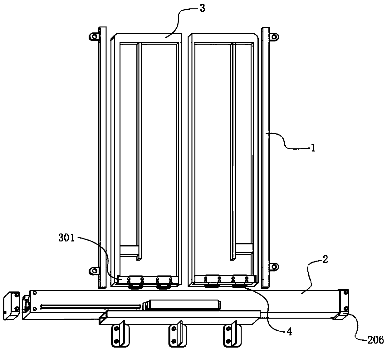
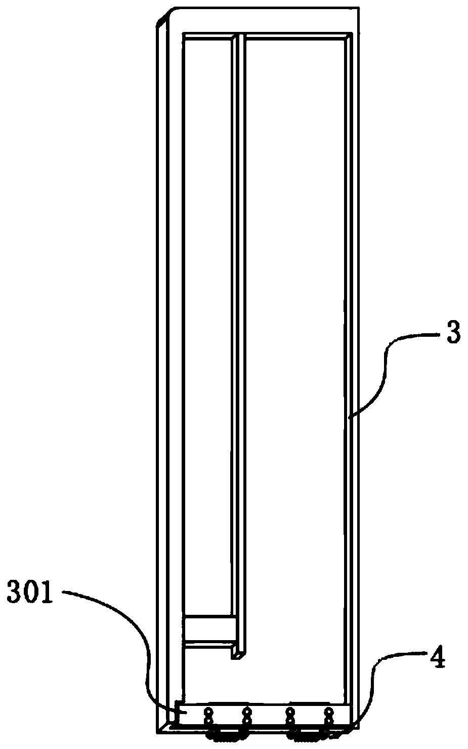
[0040] see figure 1 , the present invention provides a technical solution: a safety protection structure for an elevator hall door, including a split door leaf 3, door pockets 1 fixed on both sides of the door leaf 3 and a sill 2 below the door leaf 3, the sill 2 is fixedly installed At the bottom of the landing door opening. In practice, the door leaf 3 of the hall door is a non-powered door, which is opened by the car door, and a door lock device (not shown in the figure) is arranged above the hall door. In the prior art, only the door lock device is used to lock the two door leaves 3 lock tight.

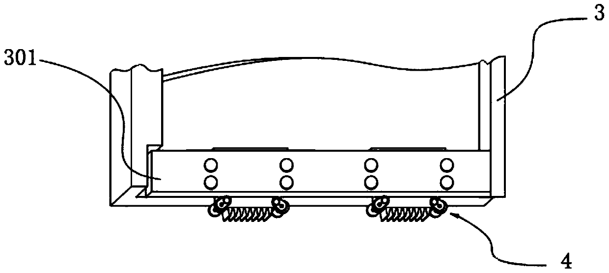
[0041] see Figure 1-3, the bottom of the door leaf 3 is detachably installed with a plurality of limit slider mechanisms 4, and the bottom of the limit slider mechanism 4 is evenly provided with upper latches 42; In the limit slider mechanism 4 , the bottom of the chute 201 is connected to the safety block 5 through lifting components, and the top of the safety block 5 is prov...

Embodiment 2

[0055] see Figure 6-8 , on the basis of Embodiment 1, a plurality of infrared emitters 7 can also be embedded and installed on the sill 2, and the infrared emitters 7 are powered by a power supply independent of the first electromagnet 61 and the second electromagnet 62, and the base 91 and A touch switch for connecting the infrared emitter 7 circuit is installed between the arc contact plates 92, the touch switch includes a first electrode 101 and a second electrode 102, the first electrode 101 is located at the bottom of the base 91, and the second electrode 102 is located at the T At the bottom of the type block 9201, when the arc-shaped contact plate 92 is pressed by the bridge compartment, the first electrode 101 and the second electrode 102 contact and communicate with the power supply circuit of the infrared emitter 7 .

[0056] One of the side walls of the sill 2 is recessed with a mounting groove 205, and a plurality of infrared emitters 7 are evenly installed in the...


PUM


Abstract

The invention discloses an elevator landing door safety protection structure. The elevator landing door safety protection structure comprises opposite open type door leaves, door pockets fixed to thetwo sides of the door leaves and a sill located below the door leaves. The sill is fixedly installed at the bottom of an opening of a shaft landing door, a plurality of limiting sliding block mechanisms are installed below the door leaves in a detachable mode, and upper clamping teeth are evenly arranged at the bottoms of the limiting sliding block mechanisms. A sliding groove is formed in the topend face of the sill in a concave mode, the limiting sliding block mechanisms are arranged in the sliding groove in a rolling mode, safety blocks are connected with the bottom of the sliding groove through lifting components, and lower clamping teeth clamped with the upper clamping teeth are arranged at the tops of the safety blocks. A contact type switch mechanism controlling the lifting components is installed on the outer surface of the sill. When an elevator door is not stopped on the floor where the landing door is located, a power supply circuit of a first electromagnet and a second electromagnet are in a connected state all the time, the upper clamping teeth of the limiting sliding block mechanisms and the lower clamping teeth on the sill are made to be clamped under the action ofelectromagnetic force, locking below the door leaves can be achieved, and it can be avoided that the door leaves are unauthorizedly opened in a man-made malice operation situation.

Description

technical field [0001] The invention relates to the technical field of elevator hall door safety protection equipment, in particular to an elevator hall door safety protection structure. Background technique [0002] As a characteristic equipment, the safety of elevators has always been the focus of people's attention, and it is also a topic that people in the industry are constantly discussing. The elevator hall door is the only barrier to isolate the hall and the shaft, and at the same time it is the only way to connect the car and the hall. The safety of the hall door is particularly important for the operation of the elevator system. [0003] There are many types of elevator accidents, which are generally divided into top rushing, squatting bottom, door accidents and other accidents. Among them, door accidents accounted for the largest proportion. The hall door accident is mainly due to the poor contact of the hall door interlock, which causes the hall door to open wit...

Claims


Application Information

Patent Timeline
Patent Type & Authority Applications(China)
IPC IPC(8): B66B13/30B66B13/20B66B13/18B66B13/08B66B5/00
CPCB66B13/301B66B13/306B66B13/308B66B13/20B66B13/185B66B13/08B66B5/00B66B5/0006
Inventor 陈汉金刘路军陈杰克陈约克陈彬彬周伦赞陈汉丰陈灿南舒向前
Owner 北菱电梯股份有限公司
Why Eureka
Try Eureka