
A Method for Detecting AC and DC Stray Currents in Buried Pipelines

A stray current and buried pipeline technology, applied in the field of detection, can solve the problems of electromagnetic field error, unknown distance between the magnetometer probe and the pipeline, and the inability to accurately and effectively detect the magnetic field

Active Publication Date: 2022-01-28
CHINA PETROLEUM & CHEM CORP +1
View PDF6 Cites 0 Cited by
  • Summary
  • Abstract
  • Description
  • Claims
  • Application Information

AI Technical Summary

Problems solved by technology

Using this method to detect stray currents in pipelines needs to consider the following issues: (1) The buried depth of buried pipelines is not fixed, so the distance between the magnetometer probe and the pipeline is unknown, and the detection signal needs to be used to determine the buried depth of the pipeline at the detected position
(3) At present, the types of interference sources in pipelines are increasing, and there are DC interference, power frequency AC interference, and low-frequency alternating current interference. In the existing methods of using magnetometer probes for pipeline current detection, generally only DC interference is involved, and cannot After the AC-DC mixed interference is tested synchronously, the two types of interference are separated to evaluate the impact of different types of interference sources on the pipeline. Therefore, the mixed AC-DC interference of buried pipelines should be detected and separated
(4) A single magnetometer probe cannot accurately and effectively detect the magnetic field generated by the current in the pipeline. The array mode of the sensor and the accurate calculation of the electromagnetic field under the array mode need to be studied
[0004] The invention patent with the application number 201110097516.9 "Measurement method of buried pipeline depth, stray current magnitude and geomagnetic azimuth angle", the invention ignores the influence of other electromagnetic field vertical ground components during measurement. In practice, the geomagnetic field exists perpendicular to the ground At the same time, there will be a component perpendicular to the ground in the external magnetic field interference, which makes the existing method have a large error in detecting the electromagnetic field generated by the stray current of the buried pipeline

Method used


Image

  • A Method for Detecting AC and DC Stray Currents in Buried Pipelines
  • A Method for Detecting AC and DC Stray Currents in Buried Pipelines
  • A Method for Detecting AC and DC Stray Currents in Buried Pipelines

Examples


Embodiment 1

[0066] The present invention provides a buried pipeline AC and DC stray current detection method,

[0067] S1. Select the position of the buried pipeline to be detected;

[0068] S2. Arranging the three magnetometer probes in a horizontal array at equal intervals on the surface where the buried pipeline is located; the three probes are probe one, probe two and probe three in sequence;

[0069] S3. When there are AC and DC stray currents in the pipeline, probe 1, probe 2, and probe 3 respectively detect the magnetic fields at their respective positions;

[0070] S4, according to the result of S3 detection, obtain the vertical component size of external stable magnetic field interference, eliminate the vertical component influence of external stable magnetic field interference;

[0071] S5. Calculate the buried depth of the pipeline according to the results of S3 and S4;

[0072] S6. Obtain the current of the pipeline under the magnetometer probe array according to the buried ...

Embodiment 2

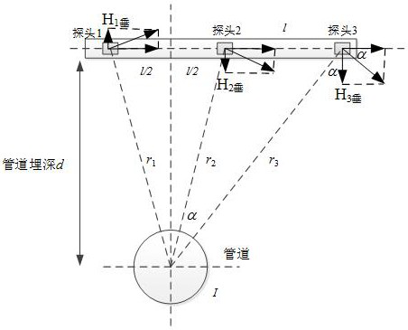
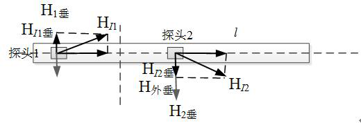
[0077] see figure 1 and figure 2 , On the basis of Example 1, three magnetic saturation magnetometer probes are arranged horizontally to form an array, the distance between the three magnetic saturation magnetometer probes is 1, and a three-component magnetic saturation magnetometer probe is selected. When detecting the AC and DC stray current of the pipeline, the buried d of the pipeline is unknown, and when the probe array is placed, the pipeline is located on the central axis of probe 1 and probe 2. When there is AC / DC stray current I in the pipeline, probe 1, probe 2, and probe 3 will all detect the magnetic fields at their respective positions, but the detected magnetic fields are disturbed by external stable magnetic fields (such as geomagnetism or other stable magnetic fields). At this time, the electromagnetic field detected by the probe cannot be directly used to calculate the pipeline current, but the influence of other stable magnetic field interference should be ...


PUM


Abstract

The invention discloses a detection method for AC and DC stray currents of buried pipelines, and relates to the technical field of detection. The magnitude of the alternating and direct current in the pipe. The beneficial effects of the invention are as follows: the invention proposes a three-component magnetic saturation magnetometer probe array method to detect AC and DC stray currents in the pipeline, and the detection data of the probes in the array can be used to realize the vertical ground interference component and the parallel ground interference under the external stable magnetic field Calculation and elimination of components, on the basis of which, pipeline depth detection can be realized. Further, the detection of AC and DC mixed stray currents in the pipeline is realized, and the AC and DC stray currents are separated to evaluate the interference conditions of the pipeline by the AC interference source and the DC interference source respectively.

Description

technical field [0001] The invention relates to the technical field of detection, in particular to a detection method for AC and DC stray currents of buried pipelines. Background technique [0002] At present, with the large-scale construction of electrified railways, rail transit lines, high-voltage AC-DC transmission lines, etc., buried pipelines are increasingly disturbed by AC and DC stray currents, and the electrochemical corrosion of oil pipelines has caused huge economic losses and potential safety hazards. , the effective detection of AC and DC stray currents in buried steel pipelines is an important measure related to the safe operation of pipelines. The AC stray current of the buried pipeline is different from the interference source of the DC stray current. Therefore, effective detection should be carried out for the mixed AC and DC stray current of the buried pipeline. At the same time, the AC stray current and the DC stray current in the pipeline should be separ...

Claims


Application Information

Patent Timeline
Patent Type & Authority Patents(China)
IPC IPC(8): G01R19/00G01R19/14G01B7/26G01R15/14
CPCG01R19/0092G01R19/14G01R15/148G01B7/26
Inventor 王观军丛军刘海波陈健飞牛更奇韩庆彭胜利鞠梓宸
Owner CHINA PETROLEUM & CHEM CORP
Learn More