Manufacturing method of optical fiber base material, optical fiber base material, and manufacturing method of optical fiber
An optical fiber base material and a technology for a manufacturing method, which are applied in the field of optical fiber base material manufacturing, can solve problems such as difficulty in securing the length, and achieve the effect of shortening the length of the base material and realizing a longer size
- Summary
- Abstract
- Description
- Claims
- Application Information
AI Technical Summary
Problems solved by technology
Method used
Image
Examples
no. 1 approach
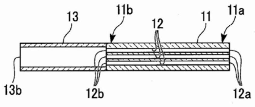
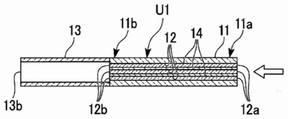
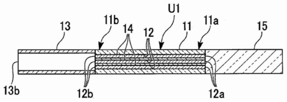
[0118] First, refer to Figure 1 to Figure 6 A first embodiment of the method for manufacturing an optical fiber preform, the optical fiber preform, and the method for manufacturing an optical fiber according to the present invention will be described.
[0119] According to the manufacturing method of the optical fiber preform of this embodiment, the Figure 6 Fiber preform 1A is shown.
[0120]
[0121] Here, in this embodiment, the direction along the central axis of the optical fiber preform 1A is referred to as the axial direction. In addition, observation on a cross-section perpendicular to the central axis is referred to as cross-sectional observation, and observation on a cross-section along the central axis is referred to as longitudinal cross-sectional observation.
[0122] In addition, each component will be described assuming that the end on the right side of the drawing is a first end portion and the end on the left side will be a second end portion. For examp...
no. 2 approach
[0193] Next, refer to Figure 8 ~ Figure 14 A second embodiment of the method for producing an optical fiber preform, the optical fiber preform, and the method for producing an optical fiber according to the present invention will be described.
[0194] In addition, in Figure 8 ~ Figure 14 in, right with Figure 1 to Figure 6 The same components are denoted by common reference numerals, and descriptions thereof are omitted or simplified.
[0195] Figure 14 It is a longitudinal sectional view showing the optical fiber preform 1B of this embodiment.
[0196] According to the manufacturing method of the optical fiber preform of this embodiment, the Figure 14 Fiber preform 1B shown.
[0197] In the manufacturing method of the optical fiber preform of this embodiment, as Figure 8 As shown, dummy quartz tubes 131 and 132 are connected to both ends of the cladding glass body 11 in the axial direction by welding (dummy quartz tube welding process).
[0198] In addition, herei...
no. 3 approach
[0247] Next, refer to Figure 15 ~ Figure 20 A third embodiment of the method for producing an optical fiber preform, the optical fiber preform, and the method for producing an optical fiber according to the present invention will be described.
[0248] Figure 20 It is a longitudinal sectional view showing the optical fiber preform 1C of this embodiment.
[0249] According to the manufacturing method of the optical fiber preform of this embodiment, the Figure 20 Fiber preform 1C shown.
[0250] Such as Figure 15 etc., in the method for manufacturing an optical fiber preform of this embodiment, a cylindrical cladding glass body 21 is used. The cladding glass body 21 forms a part of the cladding of the optical fiber drawn from the optical fiber preform 1C.
[0251] In the manufacturing method of the optical fiber preform of this embodiment, as Figure 15 As shown, first, a plurality of glass rods 23 are inserted into the through holes 22 inside the clad glass body 21 (r...
PUM
 Abstract
Description
Claims
Application Information
 - R&D
- Intellectual Property
- Life Sciences
- Materials
- Tech Scout
- Unparalleled Data Quality
- Higher Quality Content
- 60% Fewer Hallucinations
Browse by: Latest US Patents, China's latest patents, Technical Efficacy Thesaurus, Application Domain, Technology Topic, Popular Technical Reports.
© 2025 PatSnap. All rights reserved.Legal|Privacy policy|Modern Slavery Act Transparency Statement|Sitemap|About US| Contact US: help@patsnap.com


