Magnetic force buffer device

A buffer device and magnetic technology, applied in the direction of pedals, stairs, stepped structures, etc., can solve the problem of uneven force surface, achieve the effect of stable overall stress and avoid metal fatigue problems

Inactive Publication Date: 2020-02-04
FOSHAN YIGO HARDWARE LTD
View PDF10 Cites 2 Cited by
  • Summary
  • Abstract
  • Description
  • Claims
  • Application Information

AI Technical Summary

Problems solved by technology

[0003] The purpose of the present invention is to overcome the defects that the existing commonly used spring-type

Method used


Image

  • Magnetic force buffer device
  • Magnetic force buffer device
  • Magnetic force buffer device

Examples


Embodiment Construction

[0019] In order to make the purpose, technical solutions and advantages of the embodiments of the present invention clearer, the present invention will be further described below in conjunction with the embodiments and the accompanying drawings.

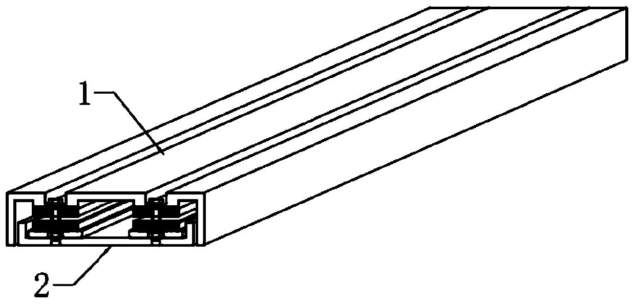
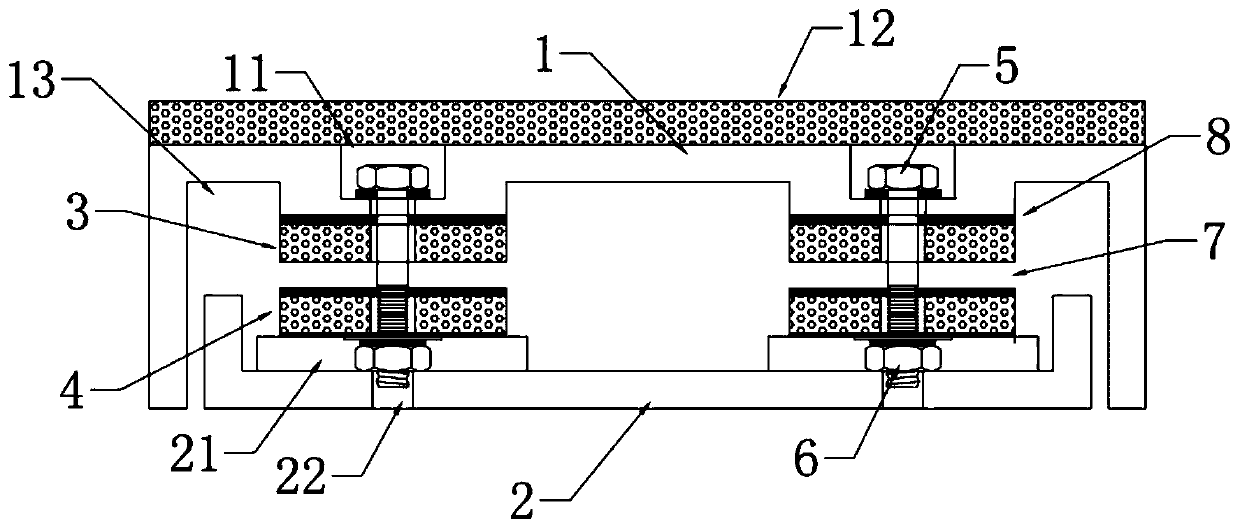
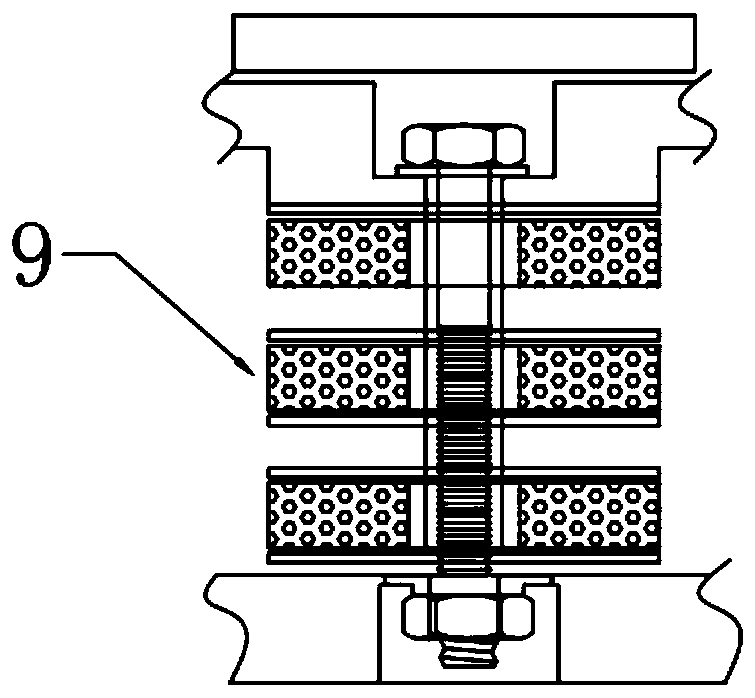
[0020] Please refer to Figure 1-4 , the magnetic buffer device includes an upper pressing block 1, a bottom plate 2, multiple sets of first magnetic strips 3, second magnetic strips 4, positioning screws 5 and positioning nuts 6, wherein the first magnetic strips 3 and the second magnetic strips The quantity of 4 is identical, and the quantity of positioning screw rod 5 and positioning nut 6 is identical, and each group of magnetic strips is assembled by several groups of positioning screw rods 5, and the positioning screw rods 5 on the first magnetic strip 3 and the second magnetic strip 4 are arranged in a straight line.

[0021] Specifically, the upper pressing block 1 is located above the bottom supporting plate 2, the first mag...


PUM


Abstract

The invention relates to the technical field of building facilities, in particular to a magnetic force buffer device. The magnetic force buffer device comprises a top pressing block, a bottom supporting plate, a plurality of sets of first magnetic stripes, second magnetic stripes, positioning screw rods and positioning nuts. The top pressing block is located above the bottom supporting plate. Thecross section of the top pressing block and the cross section of the bottom supporting plate are both in a U shape. The top pressing block and the bottom supporting plate are arranged in a matched mode. The first magnetic stripes and the second magnetic stripes are fixed into a recessed cavity of the top pressing block and a recessed cavity of the bottom supporting plate correspondingly. The samemagnetic poles of the first magnetic stripes and the second magnetic stripes are opposite, and thus magnetic repulsive force is formed. The first magnetic stripes and the second magnetic stripes are fixed into the device through the positioning screw rods. The top pressing block is suspended on the bottom supporting plate under the lifting action of the magnetic repulsive force and the limiting action of the positioning screw rods. A lifting space area is formed between the first magnetic stripes and the second magnetic stripes. According to the magnetic force buffer device, the magnetic stripes with the same magnetic poles being opposite are evenly arranged, the magnetic repulsive force is used for replacing elastic force, stable fixation is conducted, the problem of metal fatigue causedby using of elastic parts is avoided, and the stress of the device is stable on the whole.

Description

technical field [0001] The invention relates to the technical field of building facilities, in particular to a magnetic buffer device. Background technique [0002] In real life, cushioning devices are used in many occasions, such as floors (wooden floors, ceramic tiles, etc.) or the bottom of some tables and chairs, and some people even set up buffering devices under the stairs to reduce the vibration generated when walking stairs, such as the Chinese patent The application (publication number CN101775881A) discloses a non-slip and labor-saving staircase, in which a spring is arranged at the bottom of the staircase, so as to play a buffering effect. However, this kind of stairs (buffering device) is not only prone to noise when used, but also not all places on the force-bearing surface are balanced. After a period of use, the metal stretching fatigue effect will appear, resulting in uneven force on various parts, making the surface of the stairs Uneven. Contents of the i...

Claims


Application Information

Patent Timeline
IPC IPC(8): E04F11/104E04F11/02
CPCE04F11/02E04F11/1045E04F2011/1046
Inventor 吴飞
Owner FOSHAN YIGO HARDWARE LTD
Why Eureka
Try Eureka