Automatic charging system based on floor-type pantograph

An automatic charging and pantograph technology, applied in electric vehicle charging technology, charging stations, electric vehicles, etc., can solve problems such as inability to meet charging needs and limited charging speed

Pending Publication Date: 2020-02-07
LUOYANG GRASEN POWER TECH CO LTD
View PDF0 Cites 0 Cited by
  • Summary
  • Abstract
  • Description
  • Claims
  • Application Information

AI Technical Summary

Problems solved by technology

In order to ensure the normal operation of electric vehicles, it is necessary to store electricity in a timely manner. At present, most of the common charging equipment are cabinet-type charging piles, and charging guns are required to charge the vehicles. The national standard

Method used


Image

  • Automatic charging system based on floor-type pantograph
  • Automatic charging system based on floor-type pantograph

Examples


Embodiment Construction

[0011] In order to understand the above-mentioned purpose, features and advantages of the present invention more clearly, the present invention will be further described in detail below in conjunction with the accompanying drawings and specific embodiments. It should be noted that, in the case of no conflict, the embodiments of the present application and the features in the embodiments can be combined with each other.

[0012] In the following description, many specific details are set forth in order to fully understand the present invention. However, the present invention can also be implemented in other ways different from those described here. Therefore, the protection scope of the present invention is not limited by the specific details disclosed below. EXAMPLE LIMITATIONS.

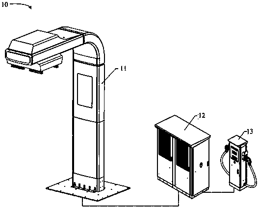
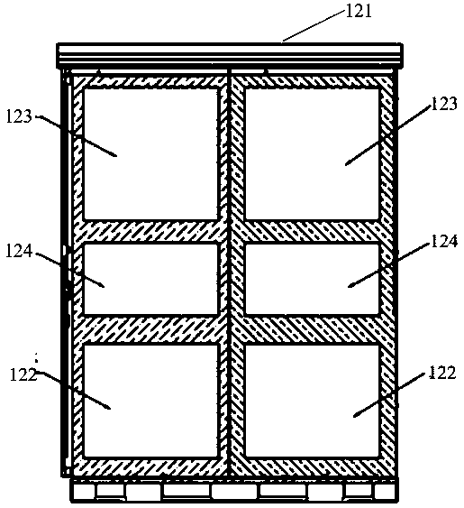
[0013] The following combination figure 1 and figure 2 The technical scheme of the present invention is described further:

[0014] Such as figure 1 As shown, the automatic charging system 10 ba...


PUM


Abstract

The invention provides an automatic charging system based on a floor-type pantograph. The automatic charging system comprises the floor-type pantograph, a charging pile and a charging pile. The floor-type pantograph and the charging pile are respectively connected to the charging pile, the floor-type pantograph comprises a floor-type pantograph rack and a pantograph body mounted on the pantographrack, and the charging pile controls the floor-type pantograph and the charging pile to work. According to the technical scheme, the system has a plurality of charging modes of the pantograph and thecharging pile and serves charging vehicles with different charging requirements, the mounting position is flexible, and actual charging requirements are met.

Description

technical field [0001] The invention relates to the technical field of charging, in particular to an automatic charging system based on a floor pantograph. Background technique [0002] With the lack of energy and environmental problems, electric vehicles (such as electric buses, electric cars, etc.) are increasingly being promoted. In order to ensure the normal operation of electric vehicles, it is necessary to store electricity in a timely manner. At present, most of the common charging equipment are cabinet-type charging piles, and charging guns are required to charge the vehicles. The national standard requires the maximum current of the charging gun to be 250A, and the charging speed is limited. Moreover, charging piles are mostly distributed in bus stations, and there are great limitations in both charging timeliness and charging sites, which cannot meet actual charging needs. Contents of the invention [0003] Based on at least one of the above technical problems, ...

Claims


Application Information

Patent Timeline
IPC IPC(8): B60L50/53B60L53/30B60L53/60B60L53/302
CPCB60L50/53B60L53/30B60L53/60B60L53/302Y02T10/70Y02T10/7072Y02T90/12
Inventor 张家书刘亚峰梁学超黄昆张伟强李庆隆邓家平张品王光辉冯鹏辉孙小微
Owner LUOYANG GRASEN POWER TECH CO LTD
Why Eureka
Try Eureka