Handle locking type mechanical lock

A technology of mechanical locks and handles, applied in the direction of handle connection, wing leaf handle, wing leaf ball handle, etc., which can solve problems such as unfavorable, complex structure, and cost reduction

Pending Publication Date: 2020-02-07
程倩雁
View PDF1 Cites 0 Cited by
  • Summary
  • Abstract
  • Description
  • Claims
  • Application Information

AI Technical Summary

Problems solved by technology

However, the existing mechanical locks either do not have this function, or the structure to realize this function is too complicated, which is not conducive to cost reduction

Method used


Image

  • Handle locking type mechanical lock
  • Handle locking type mechanical lock
  • Handle locking type mechanical lock

Examples


Embodiment

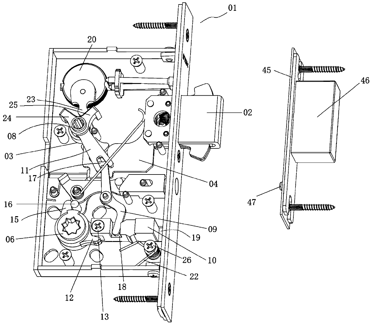
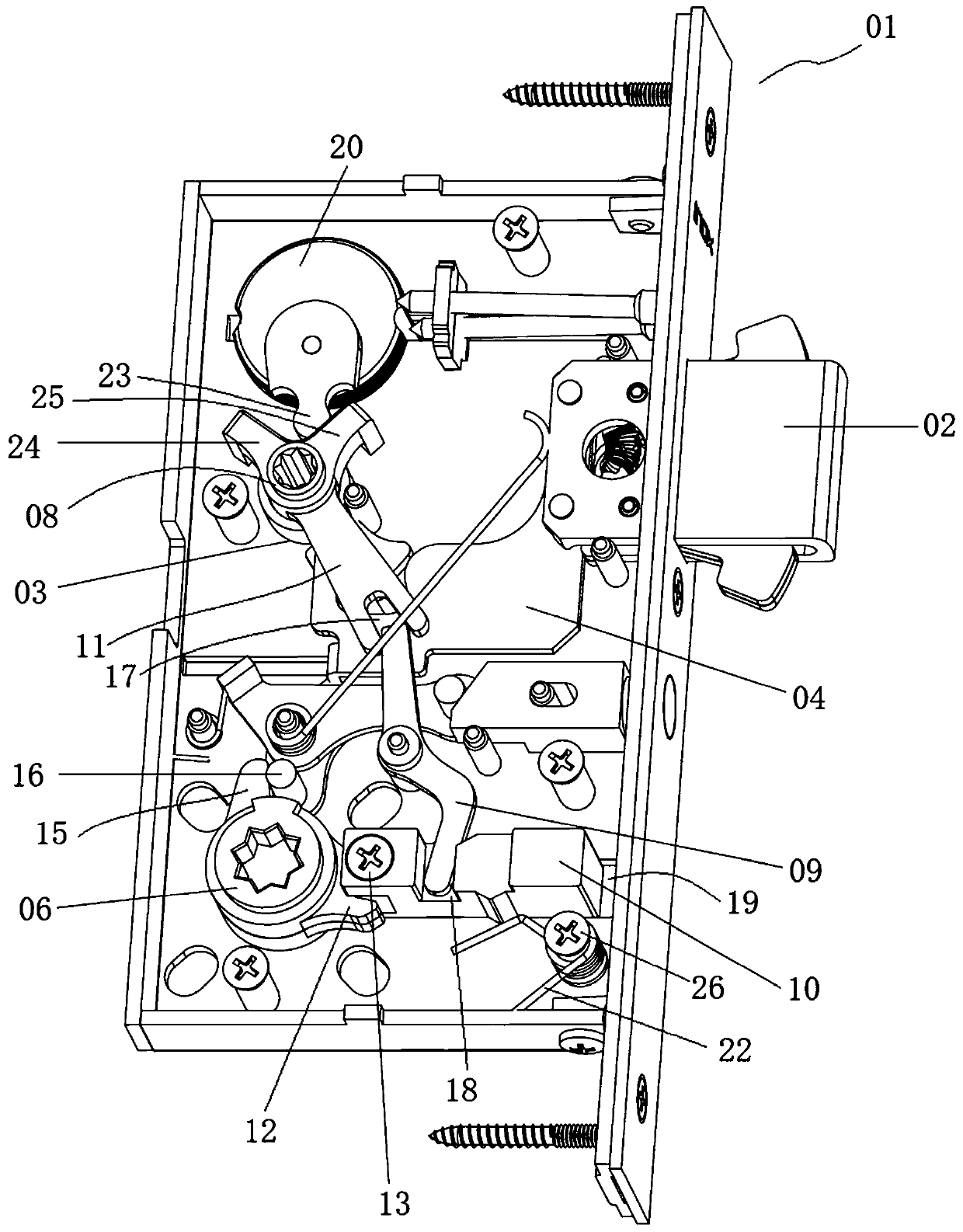
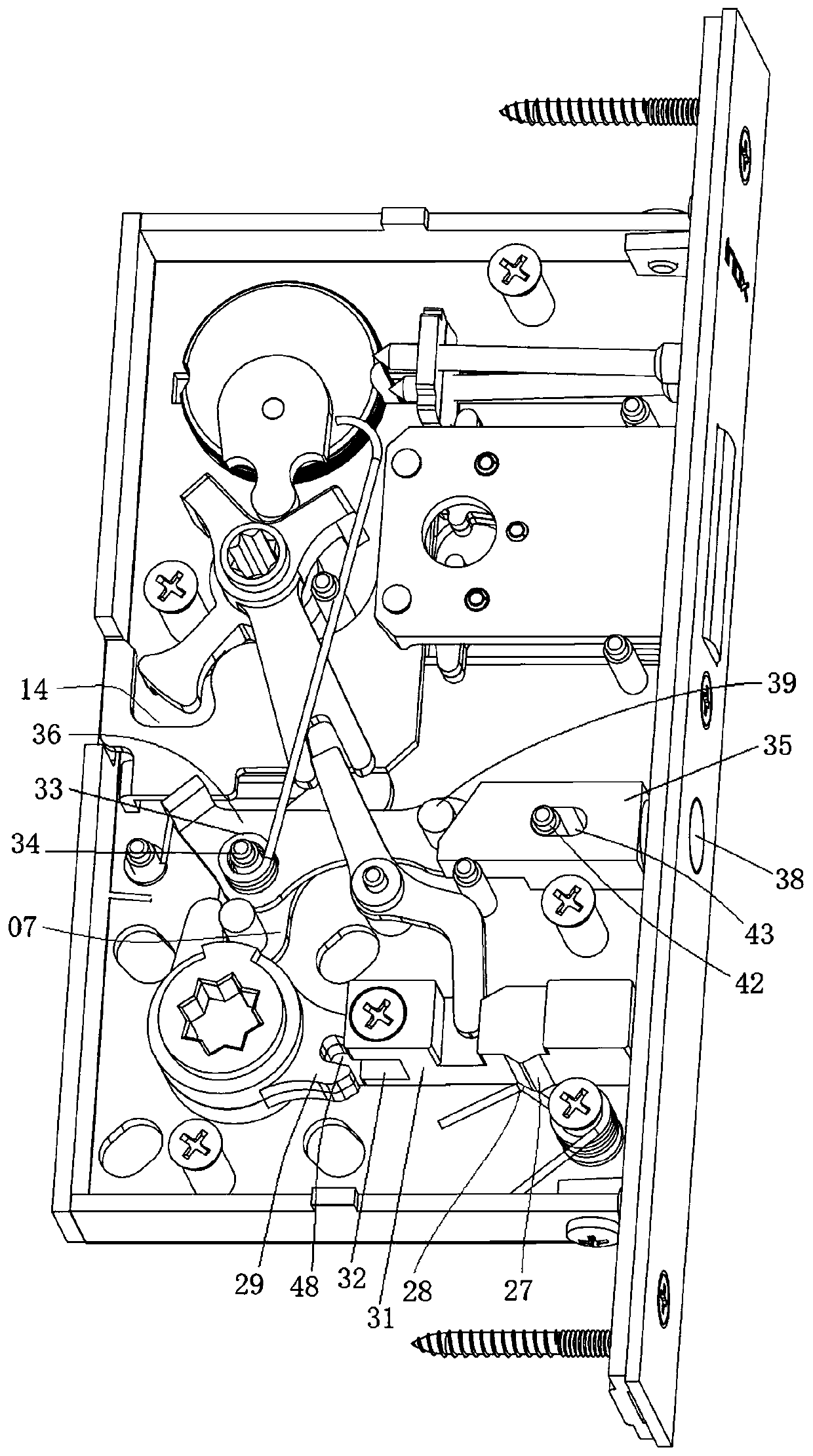
[0055] like Figure 1 to Figure 3 As shown, the handle-locking mechanical lock of this embodiment includes a lock case 01, which is provided with a dead bolt 02, a dial lever 03 and a push piece 04, and the side plate of the lock case 01 is provided with a door for the dead bolt 02 to enter and exit. Through the hole, the dial rod 03 is rotationally connected with the lock housing 01, the dial rod 03 is in transmission connection with the push piece 04, and the push piece 04 is fixedly connected with the dead bolt 02.

[0056] The mechanical lock also includes a handle transmission assembly. The handle transmission assembly includes a handle 05 located outside the lock case 01, a handle dial 06 and a handle lever 07 located inside the lock case 01; the handle 05 passes through the lock case 01 and is fixed to the handle dial 06. Even, the handle dial 06 is connected with the handle driving rod 07 in transmission, and the handle driving rod 07 is connected with the dial rod 03 ...


PUM


Abstract

The invention relates to a handle locking type mechanical lock which comprises a lock case. A spring bolt, a driving wheel rod and a push sheet are arranged in the lock case. The driving wheel rod andthe push sheet are in transmission connection, and the push sheet and the spring bolt are fixedly connected. The handle locking type mechanical lock further comprises a handle transmission assembly.The handle transmission assembly comprises a handle, a handle driving wheel and a handle driving lever. The handle penetrates through the lock case to be fixedly connected with the handle driving wheel, the handle driving wheel is in transmission connection with the handle driving rod lever and the handle driving lever and the driving wheel rod are in transmission connection. The handle locking type mechanical lock further comprises a handle locking assembly, the handle locking assembly comprises a driving wheel, a transition driving lever and a locking block, the driving wheel is provided with an extending rod, the extending rod is in transmission connection with one end of the transition driving lever, and the other end of the transition driving lever is in transmission connection with the locking block. A moving part with the confirmed moving direction is formed by the locking block and the lock case. The handle locking type mechanical lock further comprises a spring bolt locking assembly. The handle locking type mechanical lock further comprises is provided with the function of handle unlocking, when the handle needs to be locked, the functions of spring bolt locking and trigger automatic popping can be achieved, and the handle locking type mechanical lock is especially suitable for be used as a sliding door lock.

Description

technical field [0001] The invention relates to a handle locking type mechanical lock, which belongs to the technical field of mechanical locks. Background technique [0002] As far as the inventor knows, mechanical locks used in scenes such as sliding doors often have the function of controlling the retraction of the dead bolt by the handle to unlock the lock. In the long-term research, the inventor found that users increasingly hope to be able to lock the handle when needed, so that it cannot be unlocked temporarily, and unlock the handle when needed to resume its unlocking function. However, the existing mechanical locks either do not have this function, or the structure for realizing this function is too complicated, which is not conducive to cost reduction. It is urgent to develop a mechanical lock that can overcome the above problems in the prior art. Contents of the invention [0003] The main purpose of the present invention is to overcome the problems in the pri...

Claims


Application Information

Patent Timeline
Patent Type & Authority Applications(China)
IPC IPC(8): E05B3/00E05B1/00E05B15/00E05B15/10E05B17/20
CPCE05B1/003E05B3/00E05B15/00E05B15/102E05B17/2007
Inventor 程倩雁
Owner 程倩雁
Why Eureka
Try Eureka