Triggering part for unlocking and a body frame plate with an unlocking function
A technology for triggering and unlocking, which is applied in the field of frame boards, can solve problems such as inability to tilt the head or measuring head, potential safety hazards, and single triggering methods, and achieve the effects of low manufacturing cost, reasonable structure, and simple structure
- Summary
- Abstract
- Description
- Claims
- Application Information
AI Technical Summary
Problems solved by technology
Method used
Image
Examples
Embodiment 1
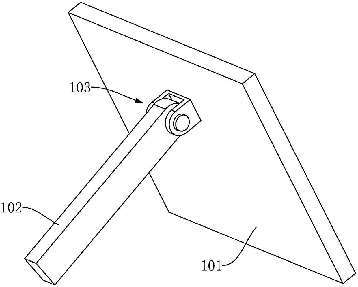
[0048] This embodiment provides a trigger part for unlocking, including a pedal 101, and the pedal 101 is used to collect (or collect) the pressure of the patient's feet or legs during unlocking, thereby triggering the unlocking. That is, when unlocking is required, the patient only needs to put his feet or legs on the pedal 101, and the pedal 101 can be squeezed by the weight of the feet or legs, thereby triggering the unlocking, which is very convenient.
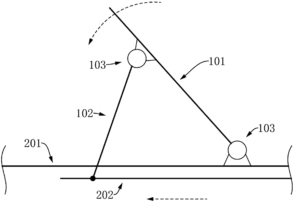
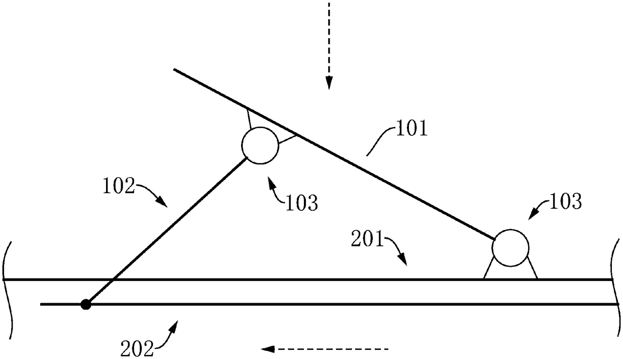
[0049] Such as figure 1 As shown, in a preferred solution provided by this embodiment, the trigger part also includes a support rod 102, one end of the support rod 102 is hinged to the pedal 101, and the other end is used to connect the transmission part 202, and the pedal 101 is used to be hinged to the body The frame plate 201, so that the pedal 101 can be fixed to the body frame plate 201.
[0050] The schematic diagram of the structure when using this trigger part to unlock is as follows: figure 2 As shown, initiall...
Embodiment 2
[0053] In this embodiment, a trigger part of another structure is provided, including a pedal 101, a support rod 102, a first positioning pin 104 and a second positioning pin 105, wherein the first positioning pin 104 is hinged to one end of the support rod 102, supporting The other end of bar 102 is hinged on pedal 101 (as Figure 5a As shown, it is usually hinged to the middle and upper part of the pedal 101), and the pedal 101 is hinged to the second positioning pin 105. The principle diagram is as follows Figure 4 shown. When installing and using the trigger part, the first positioning pin 104 is used to detachably connect the transmission part 202, the second positioning pin 105 is used to fix the installation position of the pedal 101, and the pedal 101 is used to rotate when pressed, and pass through The support rod 102 drives the transmission part 202 to move, thereby realizing the unlocking function.
[0054] Such as Figure 5a and Figure 5b As shown, in a prefe...
Embodiment 3
[0057] This embodiment provides a body frame board with an unlocking function, including a top board 301, a base 401, a transmission part 202 and the trigger part described in Embodiment 1, as Figure 7 As shown, among them,
[0058] The base 401 is provided with a chute 402, the top plate 301 is arranged above the base 401, and the top plate 301 is provided with a notch 303, such as Figure 6 As shown, the notch 303 corresponds to the chute 402 (that is, the notch 303 is arranged above the chute 402); the transmission part 202 is arranged in the chute 402, and can move a certain distance along the chute 402 under the action of an external force, And realize unlocking during the moving process; the pedal 101 is hinged on the top plate 301, so that the pedal 101 can rotate relative to the top plate 301, so as to trigger the unlocking; the support rod 102 is connected to the transmission part 202, and makes the pedal 101 stable in an inclined position, so as to facilitate the pa...
PUM
 Abstract
Description
Claims
Application Information
 - R&D
- Intellectual Property
- Life Sciences
- Materials
- Tech Scout
- Unparalleled Data Quality
- Higher Quality Content
- 60% Fewer Hallucinations
Browse by: Latest US Patents, China's latest patents, Technical Efficacy Thesaurus, Application Domain, Technology Topic, Popular Technical Reports.
© 2025 PatSnap. All rights reserved.Legal|Privacy policy|Modern Slavery Act Transparency Statement|Sitemap|About US| Contact US: help@patsnap.com


