Body-shaping exerciser
An exerciser and body sculpting technology, applied in the field of exerciser, can solve problems such as difficulty in straightening the legs, narrow space under the table, non-circulation of blood in the lower limbs, etc., achieve flexible adjustment, good body sculpting effect, and solve the effect of hunchback
- Summary
- Abstract
- Description
- Claims
- Application Information
AI Technical Summary
Problems solved by technology
Method used
Image
Examples
specific Embodiment approach 1
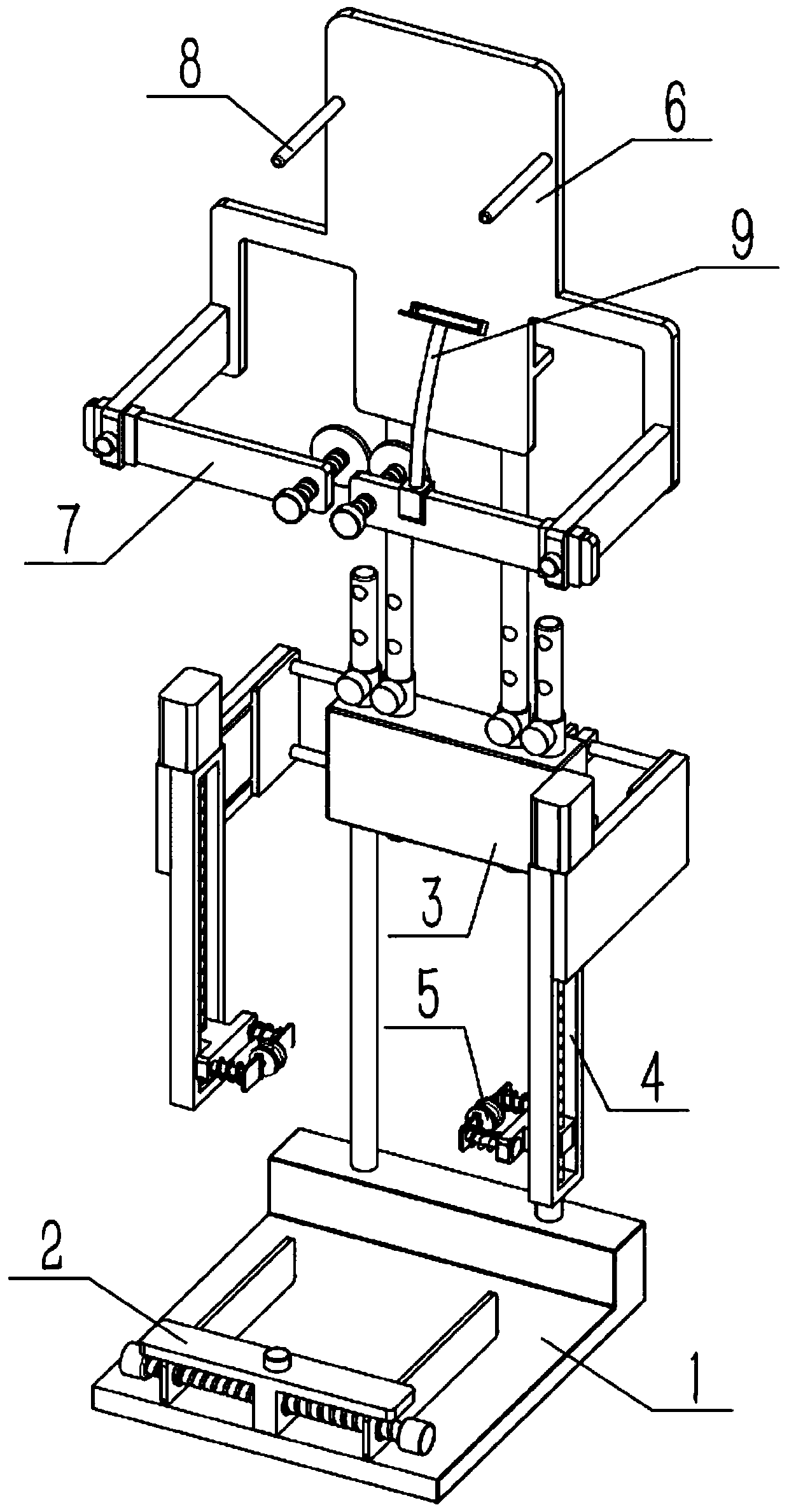
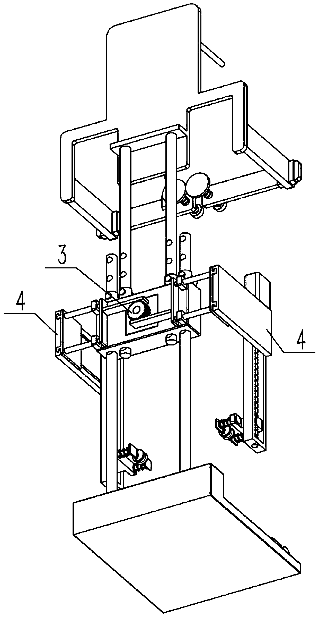
[0032] Such as Figure 1-11 As shown, a body shaping exerciser includes a foot base 1, a correction mechanism 2, a central support mechanism 3, a transfer mechanism 4, a relief mechanism 5, an upper support backrest 6 and a lower sternal corrector 7, and the foot base 1 The rear end of the upper end is connected with the correction mechanism 2, the upper end of the foot base 1 is connected with the center support mechanism 3, and there are two supply and transfer mechanisms 4, and the two supply and movement mechanisms 4 are respectively connected with the left and right ends of the center support mechanism 3, and the relief mechanism 5 There are two mirror-image symmetry, and the two relief mechanisms 5 are respectively connected to the two supply and transfer mechanisms 4, the upper support backrest 6 is connected to the center support mechanism 3, and there are two substernal correctors 7, and the two substernal The orthotic 7 is connected to the left and right sides of the...
specific Embodiment approach 2
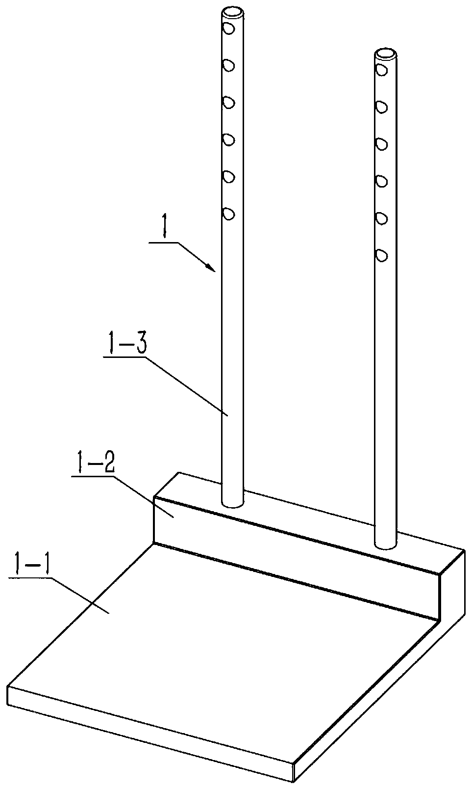
[0034] Such as Figure 1-11 As shown, the foot base 1 includes a foot placement plate 1-1, a raised contact table 1-2 and a mounting rod I1-3, and the front end of the upper end of the foot placement board 1-1 is provided with a raised contact table 1-2, there are multiple pin holes I on the installation rod I1-3, two installation rods I1-3 are provided, and the two installation rods I1-3 are fixedly connected to the left and right sides of the upper end of the raised contact table 1-2 respectively. side. The raised contact table 1-2, the central contact table 3-1 and the rear end faces of the backrest 6-1 are arranged coincidently.
specific Embodiment approach 3
[0036] Such as Figure 1-11 As shown, the correction mechanism 2 includes a T-shaped main frame 2-1, a rotating rod 2-2, a positioning screw 2-3 and a correction plate 2-4, and the middle part of the upper end of the T-shaped main frame 2-1 is provided with threads Hole I, the middle part of the lower end of the T-shaped main frame 2-1 is rotatably connected to the rotating rod 2-2, and the threaded hole I communicates with the middle part of the rotating rod 2-2. Screw threads, the two external threads have opposite thread directions, and the positioning screw 2-3 is threaded to fix the middle part of the rotating rod 2-2 by the pre-tightening force generated in the threaded hole 1. This pre-tightening force is the positioning screw 2 -3 is produced by contact with the middle part of the rotating rod 2-2, two correction plates 2-4 are provided, and the rear ends of the two correction plates 2-4 are respectively threaded with the external threads on the two rotating rods 2-2, ...
PUM
 Abstract
Description
Claims
Application Information
 - R&D
- Intellectual Property
- Life Sciences
- Materials
- Tech Scout
- Unparalleled Data Quality
- Higher Quality Content
- 60% Fewer Hallucinations
Browse by: Latest US Patents, China's latest patents, Technical Efficacy Thesaurus, Application Domain, Technology Topic, Popular Technical Reports.
© 2025 PatSnap. All rights reserved.Legal|Privacy policy|Modern Slavery Act Transparency Statement|Sitemap|About US| Contact US: help@patsnap.com


