Node snaps for smart device pulling rigging

A technology of pulling rigging and intelligent equipment, which is applied in the field of wear-resistant buckles and node buckles, which can solve the problems of affecting transmission accuracy and strength, chain wear and contact points, and long replacement time, so as to improve service life and fast installation Replacement, simple structure effect

Active Publication Date: 2020-10-27
XUZHOU OUBAI RUI INTELLIGENT EQUIP CO LTD
View PDF5 Cites 0 Cited by
  • Summary
  • Abstract
  • Description
  • Claims
  • Application Information

AI Technical Summary

Problems solved by technology

[0002] At present, in mechanical engineering, slings such as chains are often used to drive or pull smart devices. The chain is formed by continuous nesting of multiple suspension rings. When a force is applied, the bonding surface between two adjacent suspension rings Carry out frictional rotation. During the friction process, because the material of the lifting ring is the same, the size of the wear is reduced, which affects the transmission accuracy and strength. At present, the above problems are mainly replaced by replacing the lifting ring or the entire chain, which is costly and takes a long time to replace. , the existing tensioning structure will be used to tension the loose chain, but the problem of the contact point of the chain wear has not been solved, and there is no protection device between the rings at present

Method used


Image

  • Node snaps for smart device pulling rigging
  • Node snaps for smart device pulling rigging
  • Node snaps for smart device pulling rigging

Examples


Embodiment Construction

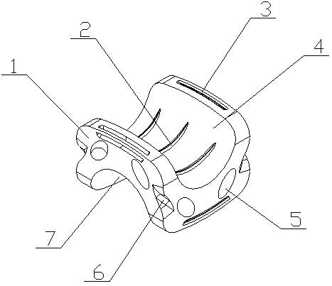
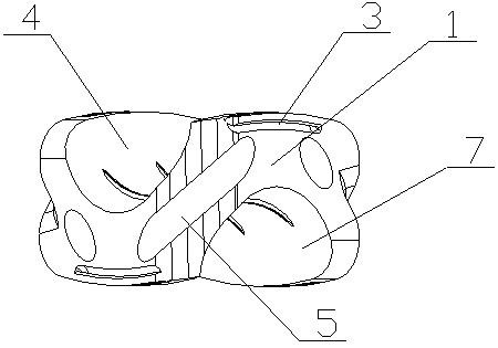
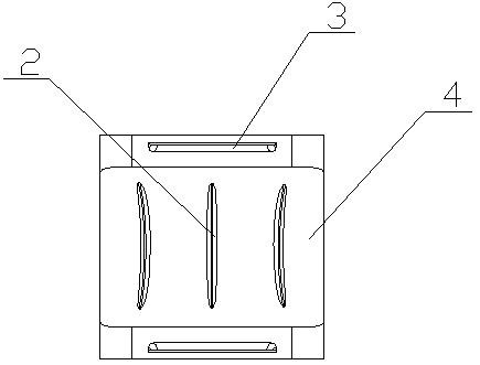
[0017] The node buckle used in the smart device pulling rigging of the present invention is realized in this way, consisting of the main body buckle (1), the friction strip (2), the fixed pull groove (3), the upper clamp groove (4), the buffer hole (5 ), bending slot (6), lower card slot (7), lower ring (8) and upper ring (9), the upper side of the main buckle (1) has an arc-shaped upper card slot (4) , the lower side of the main body buckle (1) is provided with an arc-shaped lower slot (7), the central axis of the upper slot (4) is perpendicular to the central axis of the lower slot (7), and the upper A plurality of friction strips (2) are equidistantly arranged on the groove wall of the card slot (4), and the friction strips (2) extend along the arc direction of the upper card slot (4), and the lower card slot (7) A plurality of friction strips (2) are equidistantly arranged on the groove wall, and the friction strips (2) extend along the arc direction of the lower card slot...


PUM


Abstract

The invention discloses a joint clamping buckle for a tractive rigging of intelligent equipment. The joint clamping buckle is used on a tractive chain of the intelligent equipment, carries out skid and wear resistance on a connecting point of a hoisting ring, separates connecting and fitting positions of the hoisting ring for protection and can reduce wear. The joint clamping buckle is a wearproofliner clamping buckle and is characterized in that an arc shaped upper clamping groove is formed in the upper side face of a main body buckle; an arc shaped lower clamping groove is formed in the lower side face of the main body buckle; the central axis of the upper clamping groove is perpendicular to that of the lower clamping groove; a plurality of friction strips are arranged on the groove wall of the upper clamping groove at equal intervals and extend in the arc shape direction of the upper clamping groove; a plurality of friction strips are arranged on the groove wall of the lower clamping groove at equal intervals and extend in the arc shape direction of the lower clamping groove; two fixed broached grooves are formed in the upper side face of the main body buckle and are formed inthe two sides of the opening of the upper clamping groove separately; and two fixed broached grooves are formed in the lower side face of the main body buckle and are formed in the two sides of the opening of the lower clamping groove separately.

Description

technical field [0001] The invention relates to a node buckle for a smart device pulling rigging, which relates to a buckle used on a smart device pulling chain to prevent slipping and wear resistance at a connection point of a suspension ring, and belongs to the field of mechanical engineering. In particular, it relates to a wear-resistant buckle which is stuck on the lifting ring of the pulling chain and can separate the connection and lamination positions of the lifting ring for protection and reduce wear. Background technique [0002] At present, in mechanical engineering, slings such as chains are often used to drive or pull smart devices. The chain is formed by continuous nesting of multiple suspension rings. When a force is applied, the bonding surface between two adjacent suspension rings Carry out frictional rotation. During the friction process, because the material of the lifting ring is the same, the size of the wear is reduced, which affects the transmission acc...

Claims


Application Information

Patent Timeline
Patent Type & Authority Patents(China)
IPC IPC(8): B66C1/12
CPCB66C1/125
Inventor 不公告发明人
Owner XUZHOU OUBAI RUI INTELLIGENT EQUIP CO LTD
Why Eureka
Try Eureka