Supercharge Your Innovation With Domain-Expert AI Agents!

Card edge connector having a contact positioner

A card edge connector and locator technology, applied in the direction of connection, contact parts, fixed/insulated contact components, etc., can solve problems affecting the electrical performance of card edge connectors

Active Publication Date: 2020-02-11
TE CONNECTIVITY CORP
View PDF3 Cites 0 Cited by
  • Summary
  • Abstract
  • Description
  • Claims
  • Application Information

AI Technical Summary

Problems solved by technology

However, this extra length of contact at the end of the contact beyond the mating interface of the contact creates an electrical stub that affects the electrical performance of the card edge connector.

Method used


Image

  • Card edge connector having a contact positioner
  • Card edge connector having a contact positioner
  • Card edge connector having a contact positioner

Examples


Embodiment Construction

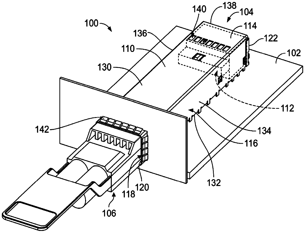
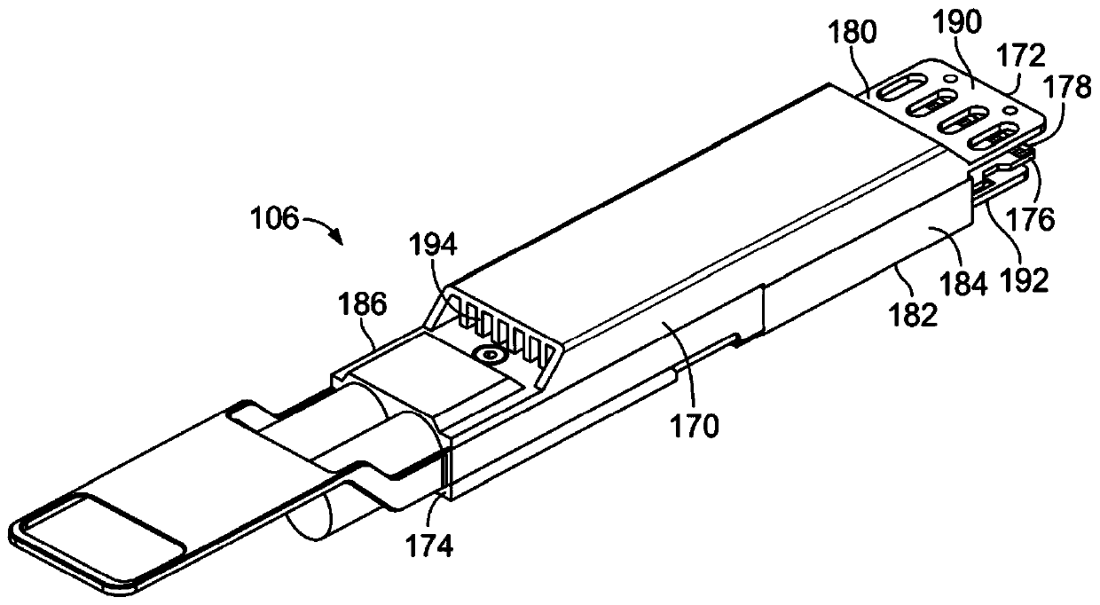
[0015] figure 1 is a front perspective view of a communication system 100 formed in accordance with an exemplary embodiment. The communication system includes a main circuit board 102 and a receptacle connector assembly 104 mounted to the main circuit board 102 . Pluggable modules 106 (in figure 2 fully shown in ) is configured to be electrically connected to the receptacle connector assembly 104. The pluggable module 106 is electrically connected to the main circuit board 102 through the socket connector assembly 104 .

[0016] In the exemplary embodiment, the receptacle connector assembly 104 includes a receptacle cage 110 and a card edge connector 112 (shown in phantom) adjacent to the receptacle cage 110 . For example, in the illustrated embodiment, card edge connector 112 is received within receptacle cage 110 . In other various embodiments, the card edge connector 112 may be located behind the receptacle cage 110 . In various embodiments, the receptacle cage 110 is...


PUM


Abstract

A card edge connector (112) includes a housing (200) and a contact assembly (202). The housing has a cavity (204), a card slot (216) and a chamber (320) adjacent the card slot. The card slot receivesa card edge (178) of a module circuit board (176) of a pluggable module (106). The contact assembly has a contact holder (230), first contacts (240) held by the contact holder (300), and a contact positioner. The contact positioner is forward of the contact holder and located in the chamber for receiving mating ends of the first contacts. The contact positioner is movable in the chamber relative to the contact holder and the housing between an inward position and an outward position. The contact positioner moves the mating ends of the first contacts outward from the card slot as the contact positioner is moved from the inward position to the outward position.

Description

technical field [0001] The subject matter herein relates generally to card edge connectors for communication systems. Background technique [0002] Some communication systems utilize communication connectors, such as card edge connectors, to interconnect various components of the system for data communication. Some known communication systems use pluggable modules, such as I / O modules, that are electrically connected to card edge connectors. The pluggable module has a module circuit board with a card edge that mates with the card edge connector during a mating operation. Each card edge connector has an upper row of contacts and a lower row of contacts for mating with a corresponding circuit board. The contacts are typically bent at the mating end to provide a large lead-in to the circuit board during mating to prevent mechanical stubbing and damage to the contacts during mating. However, this extra length of the contacts at the ends of the contacts beyond the mating inter...

Claims


Application Information

Patent Timeline
Patent Type & Authority Applications(China)
IPC IPC(8): H01R13/11H01R13/42H01R12/71
CPCH01R13/11H01R13/42H01R12/714H01R12/721H01R12/722H01R12/7005H01R12/73
Inventor M.J.菲利普斯R.R.亨利
Owner TE CONNECTIVITY CORP
Features
  • R&D
  • Intellectual Property
  • Life Sciences
  • Materials
  • Tech Scout
  • Unparalleled Data Quality
  • Higher Quality Content
  • 60% Fewer Hallucinations
Learn More