Dosing valve

A metering valve and nozzle technology, applied in the field of metering valves, can solve the problems of increased wear and achieve the effect of improving spring force and reliable sealing

Active Publication Date: 2022-03-04
ROBERT BOSCH GMBH
View PDF8 Cites 0 Cited by
  • Summary
  • Abstract
  • Description
  • Claims
  • Application Information

AI Technical Summary

Problems solved by technology

The load on the seal seat increases with increasing spring force, which leads to an increased amount of wear on the seal which is already rated as critical

Method used


Image

  • Dosing valve
  • Dosing valve
  • Dosing valve

Examples


Embodiment Construction

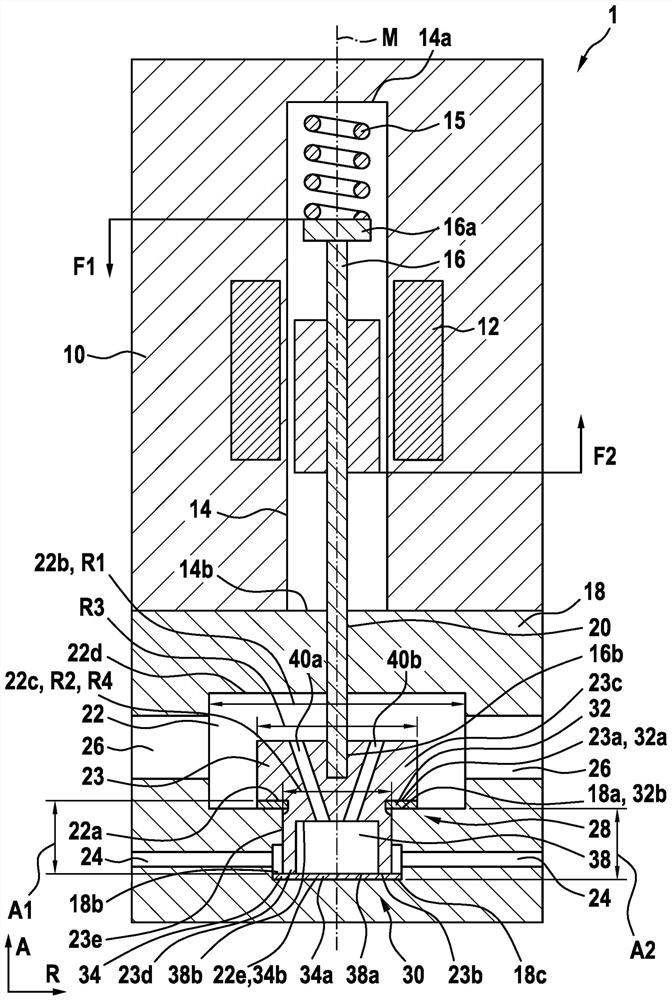
[0031] figure 1 A cross-sectional view of a metering valve for supplying gas to a fuel cell according to a preferred embodiment of the invention is shown in the closed state.

[0032]The metering valve 1 for supplying gas to a fuel cell has a base body 10 . An electromagnet 12 is arranged in the base body 10 . The base body 10 has a blind hole 14 , on a closed end 14 a of which a first spring element 15 is supported. Furthermore, the metering valve 1 has a plug-in armature 16 which is displaceably seated in the blind bore 14 . The plug-in armature 16 is loaded with a spring force F1 by the first spring element 15 at the first axial end section 16 a.

[0033] Furthermore, the metering valve 1 has a nozzle 18 which is connected to the base body 10 in the region of the open end 14 b of the blind hole 14 . The plug-in armature 16 is guided through a first bore 20 formed in the nozzle 18 . Furthermore, the plug-in armature 16 is connected at the second axial end section 16 b t...


PUM


Abstract

The invention relates to a metering valve (1) for supplying gas to a fuel cell, wherein the closing element (23) has a first abutment surface (23a), which can be abutted against all On the first abutment surface (18a) of the nozzle (18) arranged adjacent to the third hole (26) of the nozzle (18), for forming the first sealing seat (28), and wherein, the The closing element (23) has a second abutment surface (23b), which can be abutted against a second hole (24) of the nozzle (18) adjacent to the nozzle (18) The second abutment surface (18b) arranged on the ground is used to form the second sealing seat (30).

Description

technical field [0001] The invention relates to a metering valve for feeding gas to a fuel cell. Background technique [0002] A fuel cell system conventionally comprises a fuel cell having a cathode compartment and an anode compartment separated from the cathode compartment by a membrane, the fuel cell system also comprising an anode gas source, a gas supply connected to the anode gas source and the anode compartment The conveying device, the exhaust pipeline connected with the anode chamber, the cathode gas source, the gas conveying device connected with the cathode gas source and the cathode chamber, and the exhaust pipeline connected with the cathode chamber. [0003] Metering valves are conventionally arranged in the gas delivery device of the anode chamber. [0004] DE 10 2013 226 820 A1 discloses a control unit which detects the operating state of a fuel cell and actuates a metering valve as a function of the operating state, ie in particular changes the flow cross-s...

Claims


Application Information

Patent Timeline
Patent Type & Authority Patents(China)
IPC IPC(8): F16K1/34F16K1/36F16K1/42F16K31/06
CPCF16K1/34F16K1/36F16K1/42F16K31/0624F16K31/0655H01M8/04089Y02E60/50
Inventor M·库尔茨
Owner ROBERT BOSCH GMBH
Why Eureka
Try Eureka