
Driving rod locking device

A technology for transmission rods and lockers, which is applied in the direction of building fastening devices, buildings, building structures, etc., and can solve problems such as unusable, locking blocks not at the bottom, and drive lockers that cannot be installed horizontally

Pending Publication Date: 2020-02-14
3H INC
View PDF0 Cites 0 Cited by
  • Summary
  • Abstract
  • Description
  • Claims
  • Application Information

AI Technical Summary

Problems solved by technology

[0002] At present, most of the common transmission locks are installed vertically, that is, a groove is opened on the connecting rod, and the locking block is riveted on the groove with rivets. The locking block can slide on the groove. Due to gravity, the locking block is generally It is located at the bottom of the groove, and when the door and window are closed, it can be automatically locked with the limit of the lock body parts. However, sometimes due to some factors, the locking block cannot be at the bottom, resulting in the failure of the automatic locking function when the door and window are closed.
This type of transmission locker cannot be installed horizontally, and cannot be used in upper and lower hung windows and curtain wall windows

Method used


Image

  • Driving rod locking device
  • Driving rod locking device
  • Driving rod locking device

Examples


Embodiment Construction

[0017] The technical solutions claimed in the present invention will be further described in detail in conjunction with the accompanying drawings and specific embodiments.

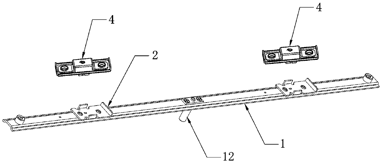
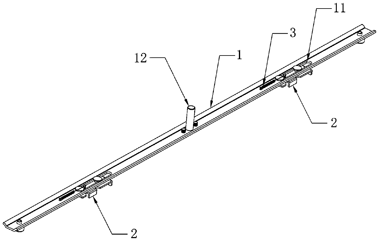
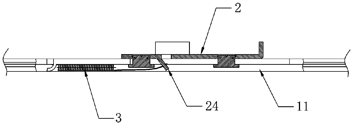
[0018] see Figure 1 to Figure 5 As shown, the transmission rod locker in this embodiment is used in conjunction with the dead bolt part 4, wherein the dead bolt part 4 is mounted on the window sash, and the transmission rod 1 is mounted on the window frame.

[0019] In this embodiment, the deadbolt component 4 includes a deadbolt 41, a deadbolt box 42 for accommodating the deadbolt 41, a return spring 43 for driving the deadbolt 41 to pop out, and a cover covering the deadbolt box 42. Cover plate 44 on the upper side. Wherein the lock tongue 41 has an inclined surface, and when the inclined surface of the lock tongue 41 collides with an object, it will be guided to shrink into the lock tongue box 42 .

[0020] In this embodiment, the transmission rod locker includes a transmission rod 1 and a lock seat ...


PUM


Abstract

The invention discloses a driving rod locking device. The driving rod locking device comprises a driving rod and a locking seat part arranged on the driving rod, a guiding groove extending in the driving rod in the length direction is formed in the driving rod, the locking seat part is slidably connected to the guiding groove, meanwhile, an elastic piece used for driving the locking seat part to be reset is connected between the locking seat part and the driving rod, the locking seat part comprises a locking seat main body, stopping blocks, and a limiting block, each stopping block is molded on each of the two sides of the locking seat main body, the limiting block is molded on the locking seat main body, and the limiting block and the elastic piece are correspondingly arranged at the twoends of the locking seat main body.

Description

technical field [0001] The invention relates to the technical field of architectural hardware, in particular to a transmission rod locker. Background technique [0002] At present, most of the common transmission locks are installed vertically, that is, a groove is opened on the connecting rod, and the locking block is riveted on the groove with rivets. The locking block can slide on the groove. Due to gravity, the locking block is generally It is located at the bottom of the groove, and when the door and window are closed, it can be automatically locked with the limit of the lock body parts. However, sometimes due to some factors, the locking block cannot be at the bottom, resulting in the failure of the automatic locking function when the door and window are closed. This type of transmission locker cannot be installed horizontally, and cannot be used in upper and lower hung windows and curtain wall windows. Contents of the invention [0003] The purpose of the present i...

Claims


Application Information

Patent Timeline
IPC IPC(8): E05C9/00E05C1/12
CPCE05C1/12E05C9/00
Inventor 朴永日林魏新李日明
Owner 3H INC
Learn More