A stamping die device
A technology of stamping dies and hydraulic cylinders, which is applied in the field of die devices, can solve the problems of cumbersome operation, increased cost, and insufficient functions, so as to achieve the effect of convenient operation and avoiding waste chip skipping
- Summary
- Abstract
- Description
- Claims
- Application Information
AI Technical Summary
Problems solved by technology
Method used
Image

Examples
specific Embodiment approach 1
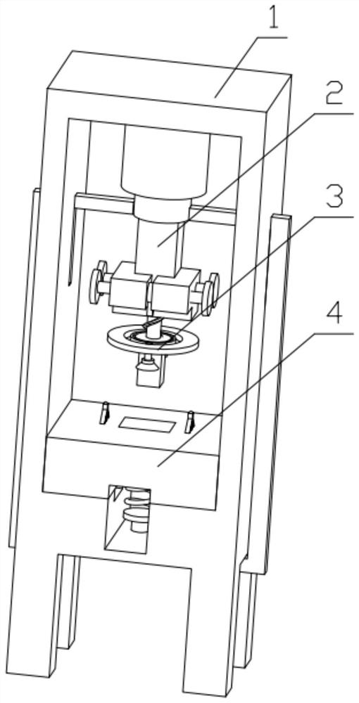
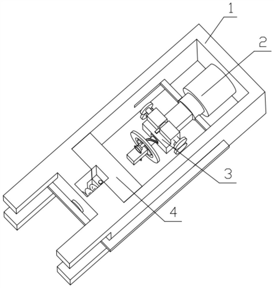
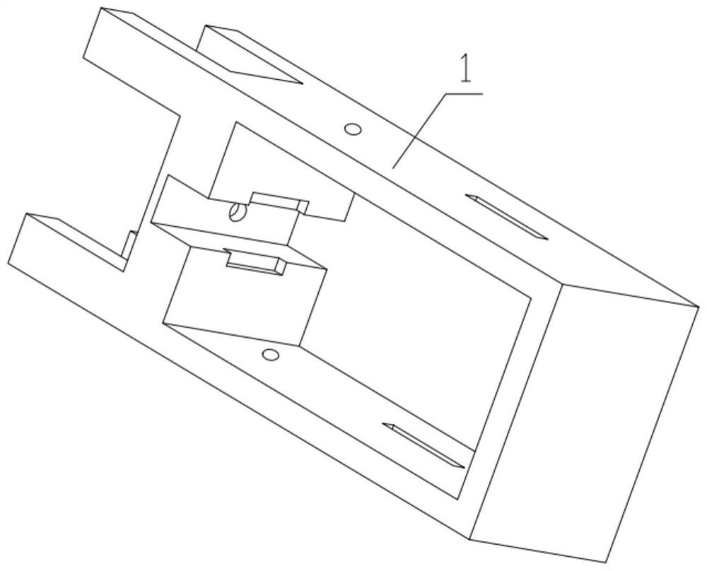
[0032] Combine below Figure 1-15 Description of this embodiment, a stamping die device, including a device frame 1, a stamping and adjusting mechanism 2, a stamping die head mechanism 3 and a stamping die seat mechanism 4, the stamping and adjusting mechanism 2 is installed on the device frame 1, stamping The die head mechanism 3 is installed on the stamping and adjusting mechanism 2 , and the stamping die seat mechanism 4 is installed on the device frame 1 .
specific Embodiment approach 2
[0034] Combine below Figure 1-15 Describe this embodiment, this embodiment will further explain the first embodiment, the stamping and adjustment mechanism 2 includes a hydraulic cylinder 2-1, a connection frame 2-2, a connection cube 2-3, a special-shaped seat 2-4, a push Rod 2-5, connecting shaft 2-6, gear 1 2-7, limit ring 2-8, gear 2 2-9, oblique clamping column 2-10, support spring 2-11, connecting frame 2-2 Fixedly installed on the output end of the hydraulic cylinder 2-1, the connecting cube 2-3 is fixedly installed on the output end of the hydraulic cylinder 2-1, the special-shaped seat 2-4 is fixedly installed on the connecting cubic piece 2-3, the gear one 2- There are two numbers of 7, the first gear 2-7 is fixedly installed on the connecting shaft 2-6, the limit ring 2-8 is fixedly installed on the connecting shaft 2-6, and the push rod 2-5 is fixedly installed on the limit ring 2-8, the limit ring 2-8 is rotatably installed on the groove provided on the special-...
specific Embodiment approach 3
[0036] Combine below Figure 1-15Describe this embodiment, this embodiment will further explain the second embodiment, the stamping die head mechanism 3 includes a connecting clip 3-1, a rotating track column 3-2, a rotating disk 3-3, a soft brush column 3- 4. The soft brush 3-5, the mold head 3-6, the rotating track column 3-2 is fixedly installed on the connecting clamp 3-1, the rotating disk 3-3 is movably installed on the rotating track column 3-2, and the mold head 3 -6 is fixedly installed on the rotating track column 3-2, the soft brush column 3-4 is fixedly installed on the rotating disk 3-3, the soft brush 3-5 is installed on the soft brush column 3-4, and the oblique clamping column 2 -10 is movably installed on the groove provided on the connecting clip 3-1, and the rotating disc 3-3 rotates along the rotating track column 3-2, so that the soft brush 3-5 rotates for cleaning.
PUM
 Abstract
Description
Claims
Application Information