Cement additive adding and weighing control system

A cement additive and control system technology, applied in weighing, measuring devices, instruments, etc., can solve the problems of large structure, inaccurate weighing data, large occupied volume, etc., and achieve a small occupied volume, simple structure and low cost. Effect

Inactive Publication Date: 2020-02-21
辰溪县丹山建材有限责任公司
View PDF0 Cites 0 Cited by
  • Summary
  • Abstract
  • Description
  • Claims
  • Application Information

AI Technical Summary

Problems solved by technology

[0005] The purpose of the present invention is: in order to solve the problems of large structure, large volume and inaccurate weighing data caused by the existing conveyer belt weighing control system to transport various cement additives, a cement additive adding Weighing Control System

Method used


Image

  • Cement additive adding and weighing control system
  • Cement additive adding and weighing control system
  • Cement additive adding and weighing control system

Examples


Embodiment 1

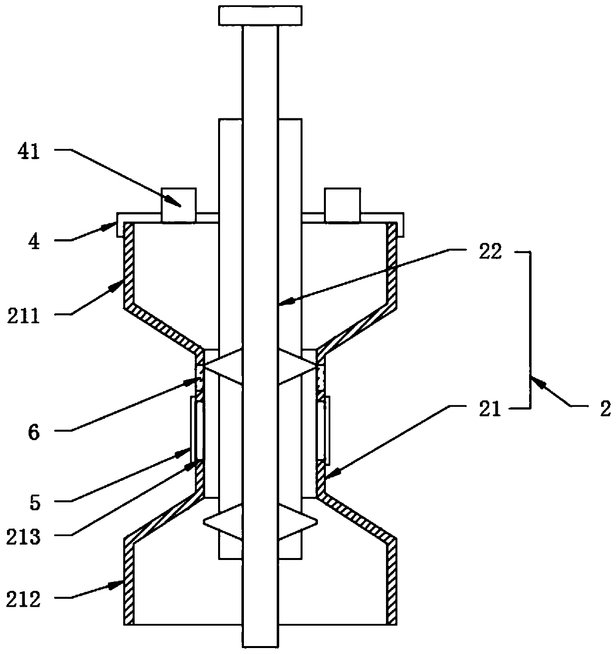
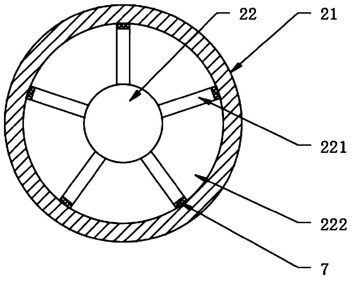
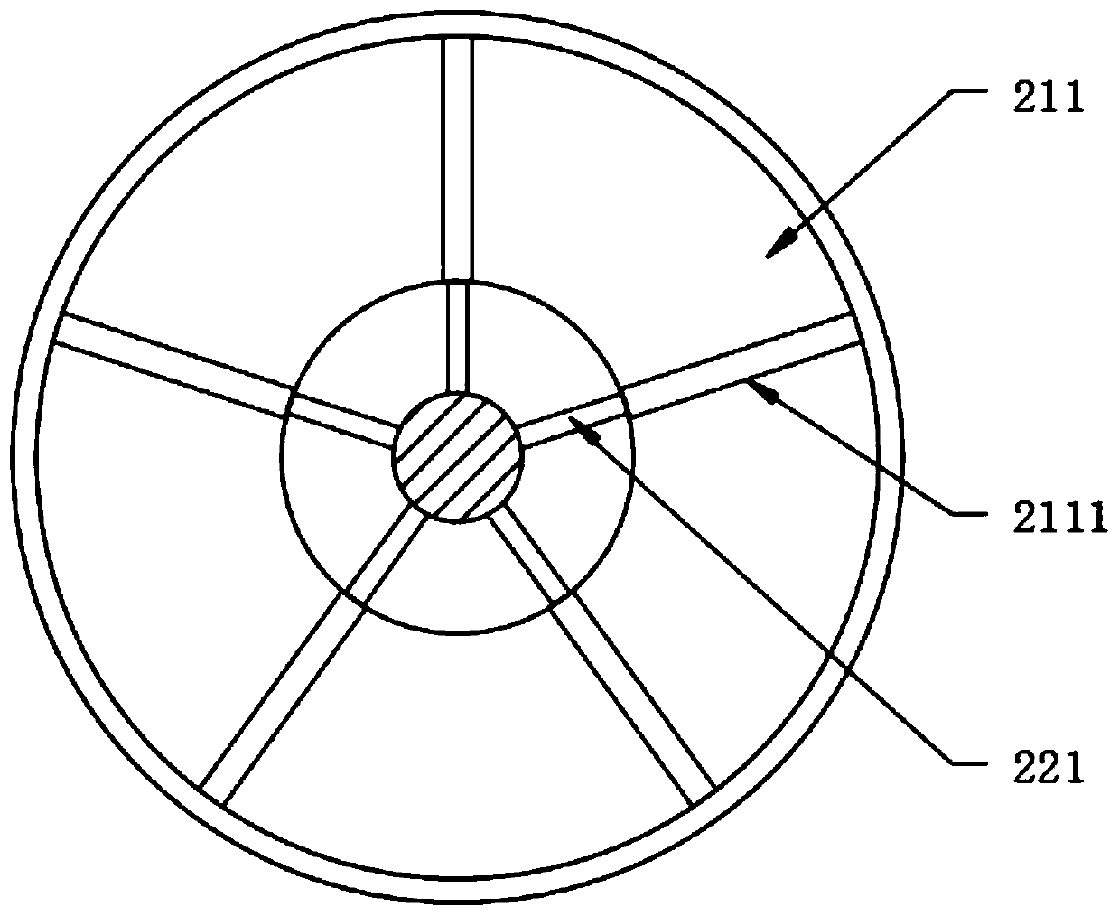
[0036] see Figure 1-5 , the present invention provides a technical solution: a cement additive weighing control system, including a pulse discharge device 2, a pulse electric telescopic rod 1 and a pulse control instrument 3, the entire control system is supported by an external support frame, and the pulse control instrument 3 is electrically connected with the pulse electric telescopic rod 1, and is used to provide pulse signals to the pulse electric telescopic rod 1, and the pulse action times per unit time of the pulse electric telescopic rod 1 can be realized through the pulse control instrument 3, and the pulse discharge device 2 includes The vertically distributed feed pipe 21 and the pulse feeding column 22 that runs through the feed pipe 21, the top of the feed pipe 21 is fixedly provided with a feed cone 211 and the bottom is fixedly provided with a discharge cone 212, the feed cone The shape cover 211 is used to place the cement additive, and the outer wall of the ...

Embodiment 2

[0038] figure 1 and Figure 4 As shown, the difference from Embodiment 1 is that the outer wall of the pulse feeding column 22 and located between two adjacent partitions 221 are provided with evenly distributed slots 2211 in the vertical direction, and one side of the weighing plate 222 is fixed A block 2221 used in conjunction with the card slot is provided, and a maintenance hole 213 is opened on the outer wall of the material guide pipe 21, and a sealing plate 5 corresponding to the maintenance hole 213 is detachably connected, and the sealing plate 5 can pass through the bolt and the material guide tube 21 outer wall connection, thus the position of the weighing plate 222 can be adjusted by opening the sealing plate 5, and then the volume between the two weighing plates 222 at the same position can be adjusted, and then the amount of single pulse feeding can be adjusted.

Embodiment 3

[0040] Such as figure 1 As shown, the difference with Embodiment 1 is that the top of the feed cone 211 is detachably connected with a cover 4, and the cover 4 is provided with evenly distributed feed pipes 41, and each feed pipe 4 and a single cement additive The discharge port is connected to facilitate feeding into the feed cone 211, while the cover 4 has the function of avoiding dust and is environmentally friendly.


PUM


Abstract

The invention discloses a cement additive adding and weighing control system, comprising a pulse discharge device, a pulse electric telescopic rod and a pulse control instrument, wherein the pulse discharge device comprises a material guide tube vertically distributed and a pulse feeding column penetrating the material guide tube, a feeding cone cover is fixedly disposed at the top of the materialguide tube and a discharging cone cover is fixedly disposed at the bottom. In the system, the volume between two weighing plates is constant, and the quantity of a cement additive is calculated according to the volume. The pulse electric telescopic rod drives the pulse feeding column to move up and down according to the operating frequency set by the pulse control instrument. When the pulse feeding column is at the upper part, multiple cement additives enter the space between the corresponding two weighing plates. After the pulse feed column moves down, the materials are quantitatively taken,and then discharged through the discharging cone cover to achieve simultaneous quantitative feeding of multiple cement additives. The system has small occupation volume, simple structure and low cost.

Description

technical field [0001] The invention relates to the technical field of cement production weighing control, in particular to a cement additive adding weighing control system. Background technique [0002] The cement additive reactor needs to add a certain amount of cement additives in the process of producing cement. There are many types of cement additives, and the dosage of additives required for cement production needs a certain proportion. [0003] At present, in the process of cement production, the delivery of various cement additives usually adopts a conveyor belt-type dosage system, and each additive corresponds to a dosage system, resulting in a large structure and a large volume; and the conveyor-type dosage system, Usually, a weighing pan is set at the bottom of the conveyor belt, and the weighing pan is weighed together with the conveyor belt instrument, which is prone to the problem of inaccurate weighing data. [0004] Therefore, the present invention provides ...

Claims


Application Information

Patent Timeline
Patent Type & Authority Applications(China)
IPC IPC(8): G01G15/00G01G19/24
CPCG01G15/001G01G19/24
Inventor 杨圣国
Owner 辰溪县丹山建材有限责任公司
Why Eureka
Try Eureka