
Door control spring with lower door opening force and more stable door closing speed

A door closing speed and sky spring technology, applied in door/window accessories, wing openers, wing closers, etc., can solve the problems of reducing the service life of the door control spring, unstable closing speed, and large inertia of the door body. , to achieve the effect of saving effort when opening the door, stable closing speed, and ensuring normal work.

Active Publication Date: 2020-02-28
嵊州市雾非雾机械设备商行
View PDF10 Cites 0 Cited by
  • Summary
  • Abstract
  • Description
  • Claims
  • Application Information

AI Technical Summary

Problems solved by technology

[0003] Although the traditional door control spring can play the role of supporting the door body, it can not play a role in assisting some heavier doors, making it more difficult for people to open it. It can be imagined that the heavier door body When closing, the traditional door control spring only plays a role of relief, and the door body has a large inertia when closing, resulting in an unstable closing speed; in addition, the existing door control spring needs to be lubricated inside after a period of use. However, oiling needs to be operated regularly by humans. If people forget, it will reduce the service life of the door control spring. Therefore, the door control sky spring with lighter door opening force and more stable door closing speed came into being.

Method used


Image

  • Door control spring with lower door opening force and more stable door closing speed
  • Door control spring with lower door opening force and more stable door closing speed
  • Door control spring with lower door opening force and more stable door closing speed

Examples


Embodiment Construction

[0022] The following will clearly and completely describe the technical solutions in the embodiments of the present invention with reference to the accompanying drawings in the embodiments of the present invention. Obviously, the described embodiments are only some, not all, embodiments of the present invention. Based on the embodiments of the present invention, all other embodiments obtained by persons of ordinary skill in the art without making creative efforts belong to the protection scope of the present invention.

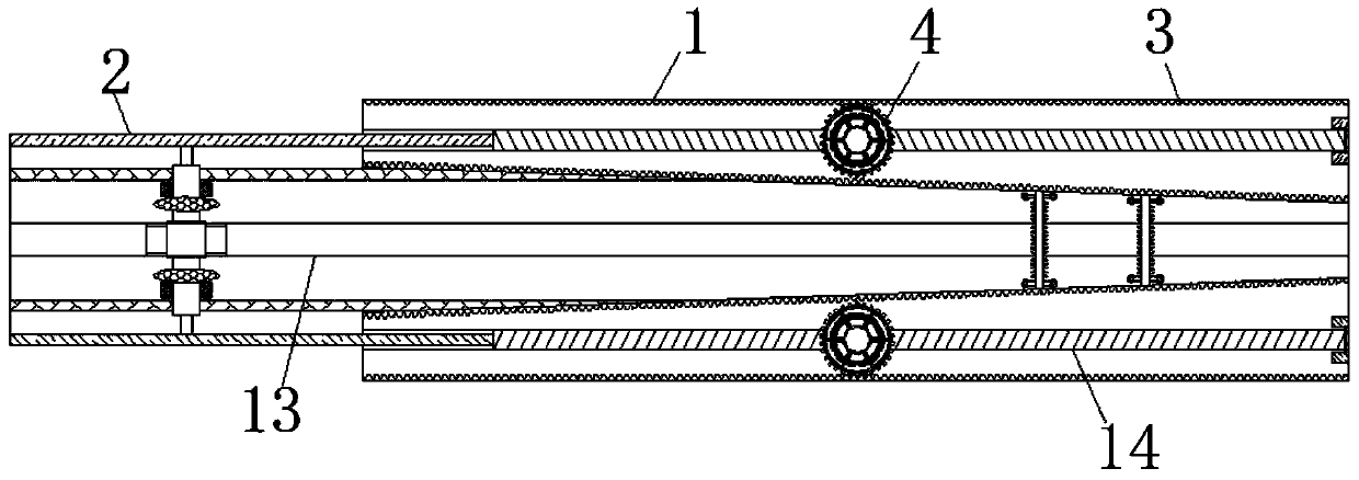
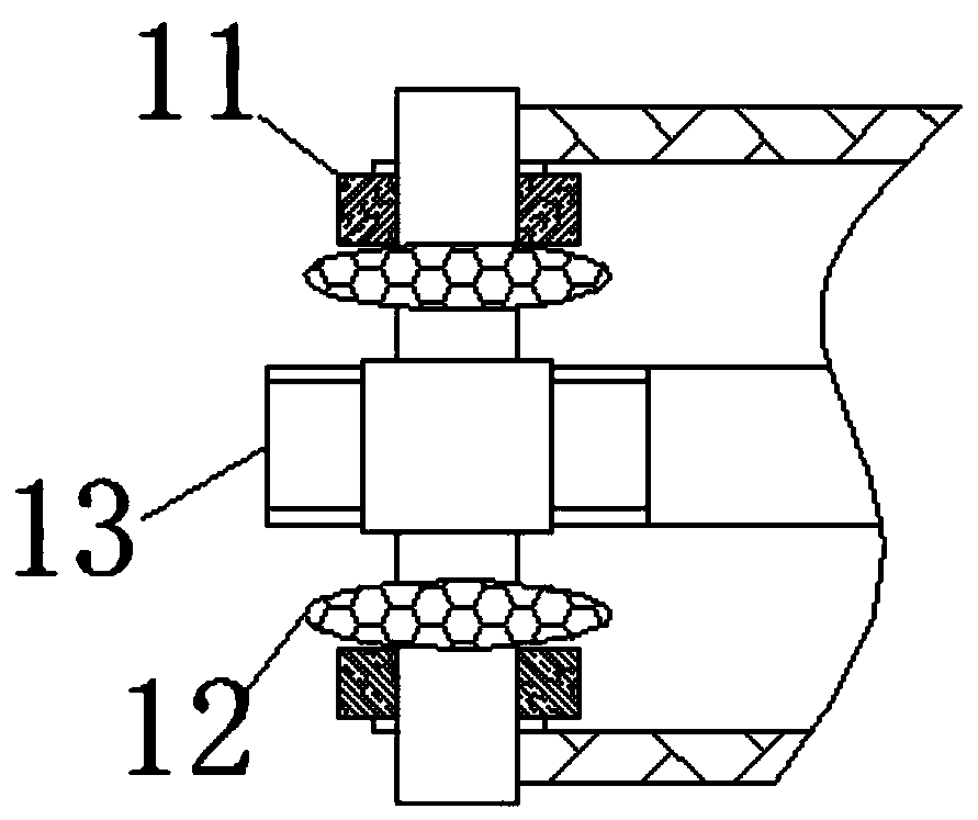
[0023] see Figure 1-6 , a door-controlled sky spring with lighter door-opening force and more stable door-closing speed, including a housing 1, characterized in that: the surface of the housing 1 is movably connected with a connecting piece 2, and the inside of the connecting piece 2 is movably connected with a push rod 11, The side of the airbag 12 away from the push rod 11 is fixedly connected with a hollow passage 13, the hollow passage 13 plays the role o...


PUM


Abstract

The invention relates to the technical field of door control springs, and discloses a door control spring with lower door opening force and more stable door closing speed. The door control spring comprises a shell and is characterized in that a connector is movably connected with the surface of the shell, a toothed plate is fixedly connected within the shell, a expanding and contracting wheel is movably connected with the surface of the toothed plate, an extruding plate is movably connected with the side, away from the toothed plate, of the expanding and contracting wheel, a compressing springis movably connected with the side, away from the expanding and contracting wheel, of the extruding plate, and a spring rod is movably connected within the expanding and contracting wheel; when the expanding and contracting wheel, the compressing spring and the extruding plate are not in contact, the spring rod loses the limiting force so as to be extended, meanwhile, the friction force between teeth, the toothed plate and the extruding plate is higher, the closing speed of a door body tends to be stable, and the elastic force of the compressing spring is higher than that of the spring rod; and the friction force between the teeth, the toothed plate and the extruding plate is gradually lower in the contraction process of the expanding and contracting wheel, and the opening force of the door body is more effort, so that the effects of the lower door opening force and more stable door closing speed are achieved.

Description

technical field [0001] The invention relates to the technical field of door control springs, in particular to a door control sky spring with lighter door opening force and more stable door closing speed. Background technique [0002] The door control spring is often used to control the opening and closing of the door body. With the continuous development of technology, in order to make the door body more anti-theft, the door body is made more and more heavy, and the door control spring is also developed. [0003] Although the traditional door control spring can play the role of supporting the door body, it can not play a role in assisting some heavier doors, making it more difficult for people to open it. It can be imagined that the heavier door body When closing, the traditional door control spring only plays a role of relief, and the door body has a large inertia when closing, resulting in an unstable closing speed; in addition, the existing door control spring needs to be...

Claims


Application Information

Patent Timeline
Patent Type & Authority Applications(China)
IPC IPC(8): E05F1/14F16N9/00
CPCE05F5/00E05Y2900/132F16N7/36F16N2270/70
Inventor 罗力川
Owner 嵊州市雾非雾机械设备商行
Learn More