Variable-frequency motor with damping effect

A frequency conversion motor and shock-absorbing effect technology, which is applied in the direction of electrical components, electromechanical devices, electric components, etc., can solve the problems of lack of buffer mechanism and motor damage in frequency conversion motors, and achieve obvious buffering effects, vibration suppression, and strong practicability

Inactive Publication Date: 2020-03-06
HUBEI WANBANG ELECTROMECHANICAL DEV
View PDF0 Cites 4 Cited by
  • Summary
  • Abstract
  • Description
  • Claims
  • Application Information

AI Technical Summary

Problems solved by technology

[0004] The purpose of the present invention is to solve the disadvantages in the prior art that the variable frequency motor lacks a buffer mechanism, and it

Method used


Image

  • Variable-frequency motor with damping effect
  • Variable-frequency motor with damping effect
  • Variable-frequency motor with damping effect

Examples


Embodiment 1

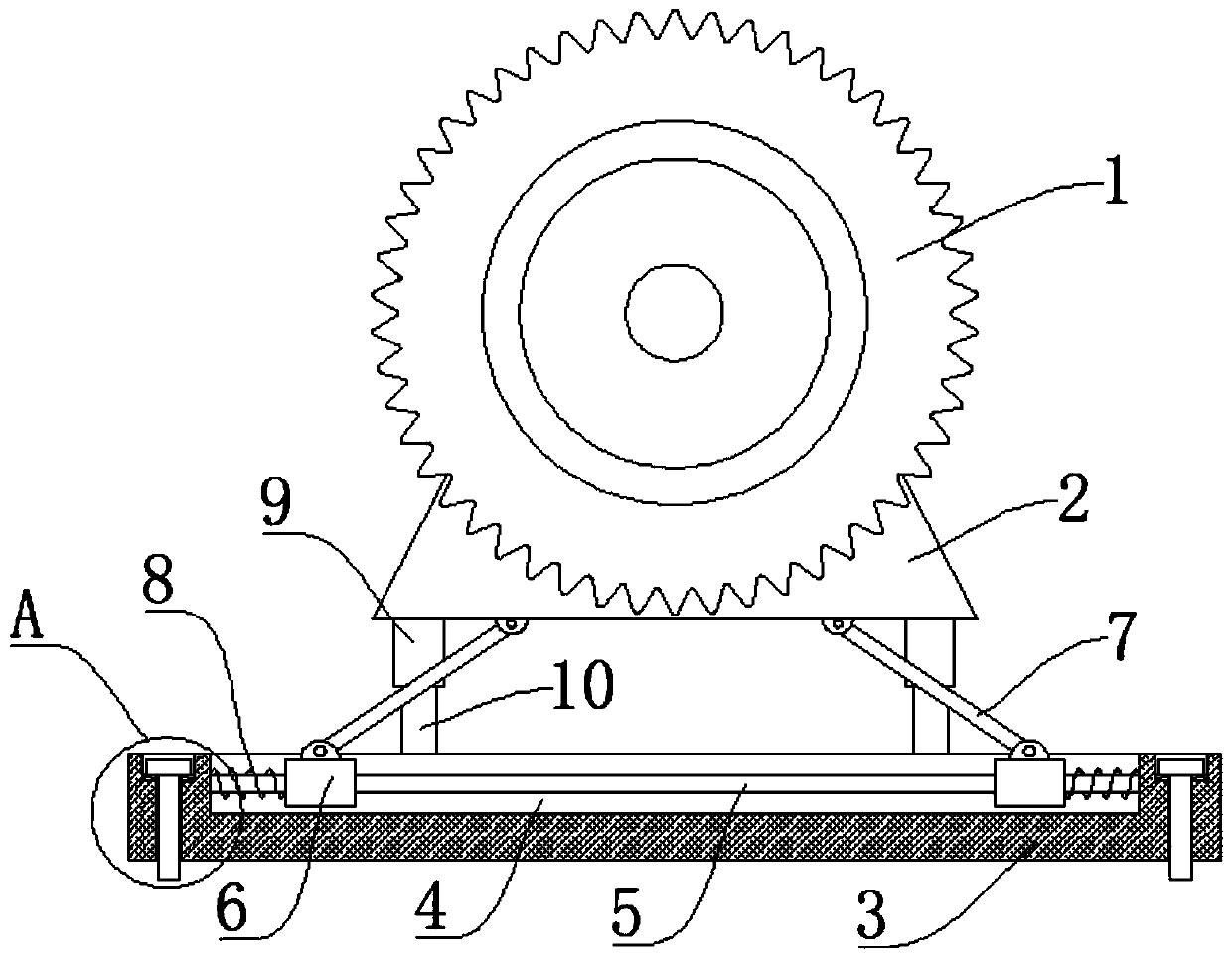
[0017] Reference Figure 1-3 , A variable frequency motor with damping effect, comprising a variable frequency motor body 1. The bottom end of the variable frequency motor body 1 is fixedly welded with a stabilizer 2. A support base 3 is arranged under the stabilizer 2, and the support base 3 and the stabilizer 2 A buffer mechanism is provided in the middle, and the buffer mechanism includes a square groove 4 opened on the top surface of the support base 3, a smooth round rod 5 is fixed in the square groove 4, a slider 6 is slid on the smooth round rod 5, and the slider 6 rotates. A support rod 7 is connected. One end of the support rod 7 away from the slider 6 is rotated and arranged under the stabilizer 2. The sliding rod 5 is sleeved with a spring 8, and the two ends of the spring 8 are perpendicular to the slider 6 and the square groove 4 respectively. Offset against the side wall, by setting the smooth round rod 5 and the slider 6, and the slider 6 is indirectly connected ...

Embodiment 2

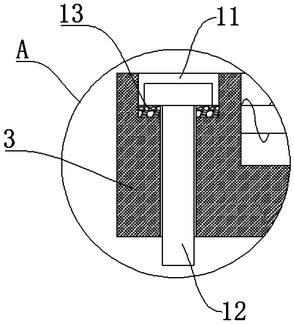
[0020] Reference image 3 As another preferred embodiment of the present invention, the difference from embodiment 1 is that a rubber gasket 13 is placed in the fixing groove 11, and the fixing bolt 12 is pressed on the rubber gasket 13. The rubber gasket 13 can be set A reverse force is exerted on the fixing bolt 12 to increase the thread friction between the fixing bolt 12 and the ground, and to prevent the fixing bolt 12 from loosening.

Embodiment 3

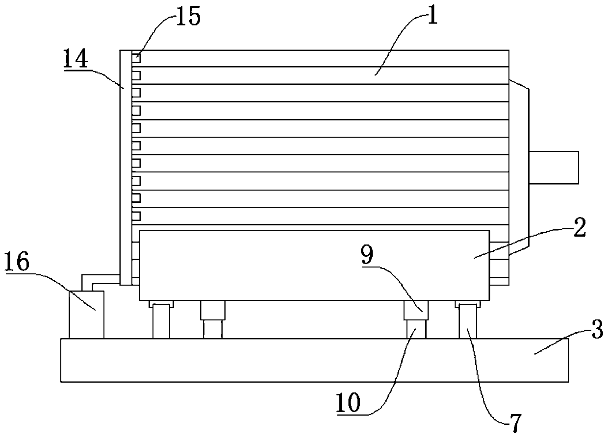
[0022] Reference figure 2 As another preferred embodiment of the present invention, the difference from embodiment 1 is that the outer side of the inverter motor body 1 is set in a wave shape, and the side of the inverter motor body 1 away from the output end is fixedly provided with a hollow ring 14, the hollow ring 14 is provided with an air outlet 15, which is located in the trough on the outside of the frequency conversion motor body 1, and an air pump 16 is fixedly installed on the supporting base plate 3. The air pump 16 and the hollow ring 14 are connected by a pipe, the air pump 16 is turned on, and the hollow ring 14 Inflate, the airflow will be discharged from the air outlet 15 at this time, and the airflow discharged from the air outlet 15 will quickly take away the heat outside the inverter motor body 1, and the outside of the inverter motor body 1 is set in a wave shape to heat the heat of the motor Ability, and the air outlet 15 is located at the trough, which rea...


PUM


Abstract

The invention relates to the technical field of variable-frequency motors, and especially relates to a variable-frequency motor with a damping effect. The variable-frequency motor comprises a variable-frequency motor body. A stabilizing part is fixedly welded to the bottom end of the variable-frequency motor body; a supporting bottom plate is arranged under the stabilizing part; and a buffer mechanism is arranged between the supporting bottom plate and the stabilizing part. The buffer mechanism comprises a square groove formed in the top surface of the supporting bottom plate, and a smooth round rod is fixedly arranged in the square groove. The smooth round rod and the sliding block are arranged, and the sliding block is indirectly connected with the variable-frequency motor, so that whenthe variable-frequency motor moves downwards, the sliding block can slide on the smooth round rod; a spring is arranged on the smooth round rod, so that when the sliding block moves, the spring is extruded, downward pressing movement of the variable frequency motor is buffered, and vibration of the variable-frequency motor is effectively restrained at the moment; and through the arrangement of a guide mechanism, the variable-frequency motor always moves in the vertical direction, and lateral deviation is avoided. The variable-frequency motor is obvious in buffering effect, high in practicability and suitable for popularization.

Description

Technical field [0001] The present invention relates to the technical field of variable frequency motors, in particular to a variable frequency motor with shock absorption effect. Background technique [0002] A variable frequency motor refers to a motor that runs continuously within the range of 10% to 100% rated speed at 100% rated load under standard environmental conditions, and the temperature rise does not exceed the motor's calibrated allowable value. [0003] When the frequency conversion motor is running, it will vibrate. Because the frequency conversion motor is directly fixed on the ground, the frequency conversion motor will directly collide with the ground when it vibrates. This will cause damage to the inside of the frequency conversion motor for a long time. We need to design a variable frequency motor with a shock absorption effect to buffer the impact between the variable frequency motor and the ground. Summary of the invention [0004] The purpose of the present i...

Claims


Application Information

Patent Timeline
IPC IPC(8): H02K5/24
CPCH02K5/24
Inventor 张军
Owner HUBEI WANBANG ELECTROMECHANICAL DEV
Why Eureka
Try Eureka