


Quick Research
Generate reliable direction feasibility study reports for your R&D in just a few steps.

Technical Q&A
Discover and master advanced knowledge NOW. Basics, ideas, possibilities, all at once.

Find Solutions
As an expert in R&D theories, this can generate solutions to your technical problems instantly.

Evaluate Feasibility
Analyze your overall solution with one click, know your potential R&D risks in advance.

Monitor Landscape
Get weekly tech updates, stay abreast of the latest tech innovations and key insights.
Connector
一种连接器、型芯的技术,应用在连接、车辆连接器、导电连接等方向,能够解决销细长等问题
- Summary
- Abstract
- Description
- Claims
- Application Information
AI Technical Summary
Problems solved by technology
Method used
Image

Examples
Embodiment approach 1
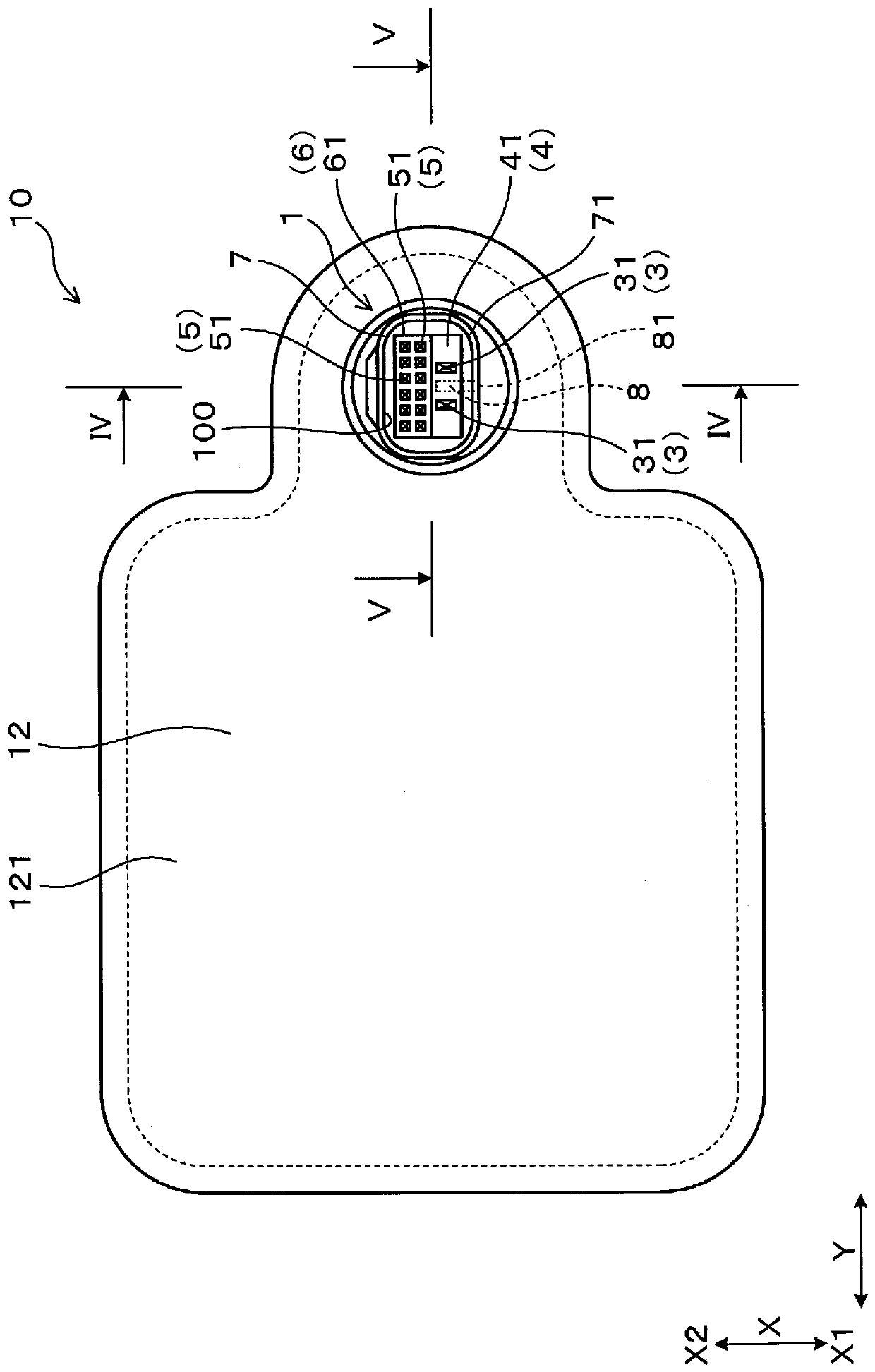
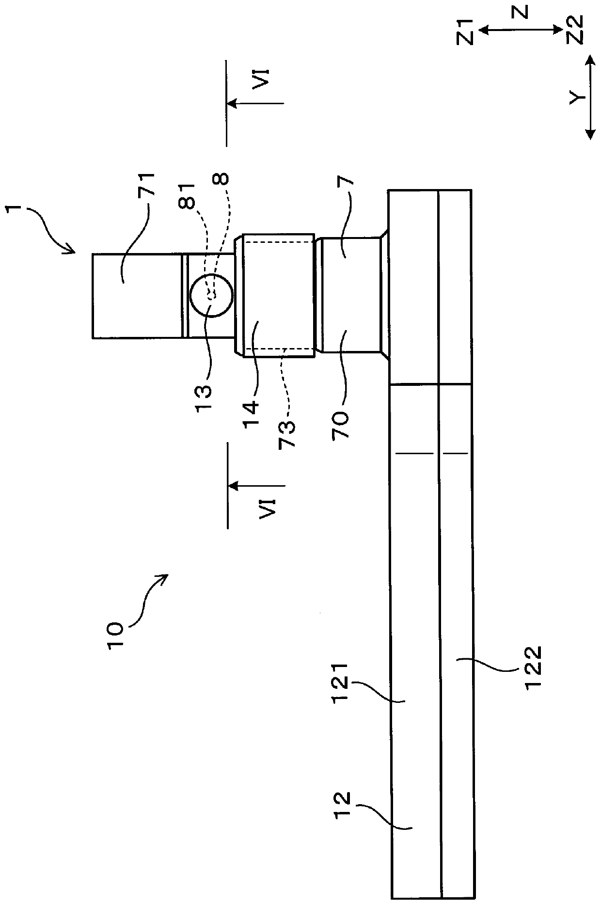
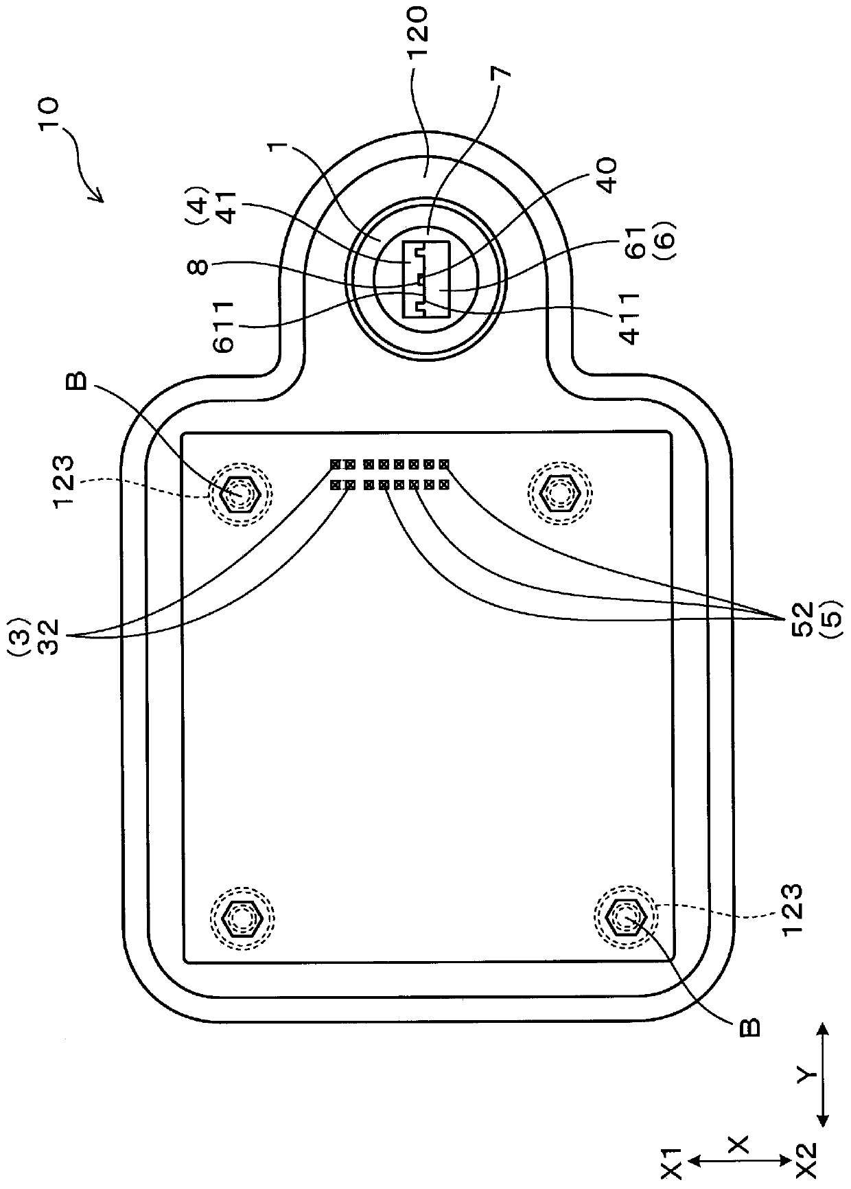
[0037] use Figure 1 to Figure 8 Embodiments of the connector will be described.
[0038] Such as Figure 5 As shown, the connector 1 is assembled in the box body 12 , and the box body 12 has an inner space 120 containing the electronic substrate 11 . Such as Figure 4 , Figure 6 As shown, the connector 1 has a plurality of first terminals 3 , a first core 4 , a plurality of second terminals 5 , a second core 6 , a housing 7 and an air passage 8 .
[0039] Such as Figure 5 As shown, the first core 4 exposes both ends of the first terminal 3 and holds the first terminal 3 . Such as Figure 4 , Figure 6 As shown, the second core 6 overlaps the first core 4 facing each other. In addition, the second core 6 exposes both ends of the second terminal 5 and holds the second terminal 5 .
[0040] Such as figure 1 , figure 2 , Figure 4 , Figure 5 As shown, the housing 7 has a cover part 71 . Such as Figure 4 As shown, the cover portion 71 surrounds one end portion ...
Embodiment approach 2
[0094] Such as Figure 9 ~ Figure 11 As shown, this form is an embodiment in which the form of the air passage 8 is changed in the first embodiment.
[0095] Such as Figure 9 , Figure 11 As shown, although the first plate portion 41 of the first core 4 has the groove portion 40, no core through hole is formed (refer to Figure 4 ~ Figure 7 etc. reference number 412). Such as Figure 9 As shown, the groove portion 40 has a first groove portion 401 extending in the Z direction and a second groove portion 402 extending from the Z1-side end of the first groove portion 401 to one side of the Y direction, and has a shape bent into an L shape. shape. The Z2-side end of the first groove portion 401 is open on the Z2 side. In addition, the end portion of the second groove portion 402 on the side opposite to the first groove portion 401 is open in the Y direction.
[0096] and, if Figure 11 As shown, the groove portion 40 formed on the overlapping surface 411 of the first pla...
Embodiment approach 3
[0103] Such as Figure 12 As shown, this method is to change the shape of the convex portion 612 of the second core 6 and change the shape of the concave portion of the first core 4 (refer to Figure 6 , Figure 7 Etc. reference numeral 413) implementation of removal.
[0104] In this form, the 2nd plate-shaped part 61 of the 2nd core 6 is equipped with the convex line part 612 which protrudes to X1 side from both end parts of a Y direction. The dimension in the Y direction of the first plate-shaped portion 41 of the first core 4 is equal to the dimension between the pair of protruding strips 612, and the first plate-shaped portion 41 of the first core 4 is arranged on the second plate-shaped portion. The inner sides of the pair of protruding strips 612 of 61 are fitted into the second plate-like portion 61 of the second core 6 . The surface on the X2 side of the first plate-shaped portion 41 is constituted by a plane perpendicular to the X direction except for the groove p...
PUM
 Abstract
Description
Claims
Application Information
 - R&D Engineer
- R&D Manager
- IP Professional
- Industry Leading Data Capabilities
- Powerful AI technology
- Patent DNA Extraction
Browse by: Latest US Patents, China's latest patents, Technical Efficacy Thesaurus, Application Domain, Technology Topic, Popular Technical Reports.
© 2024 PatSnap. All rights reserved.Legal|Privacy policy|Modern Slavery Act Transparency Statement|Sitemap|About US| Contact US: help@patsnap.com