
A Positioning Method Based on RFID and Phase Calibration

A phase calibration and positioning stage technology, applied in the field of RFID positioning, can solve problems such as positioning errors and affecting phases

Active Publication Date: 2022-05-17
TIANJIN UNIV
View PDF6 Cites 0 Cited by
  • Summary
  • Abstract
  • Description
  • Claims
  • Application Information

AI Technical Summary

Problems solved by technology

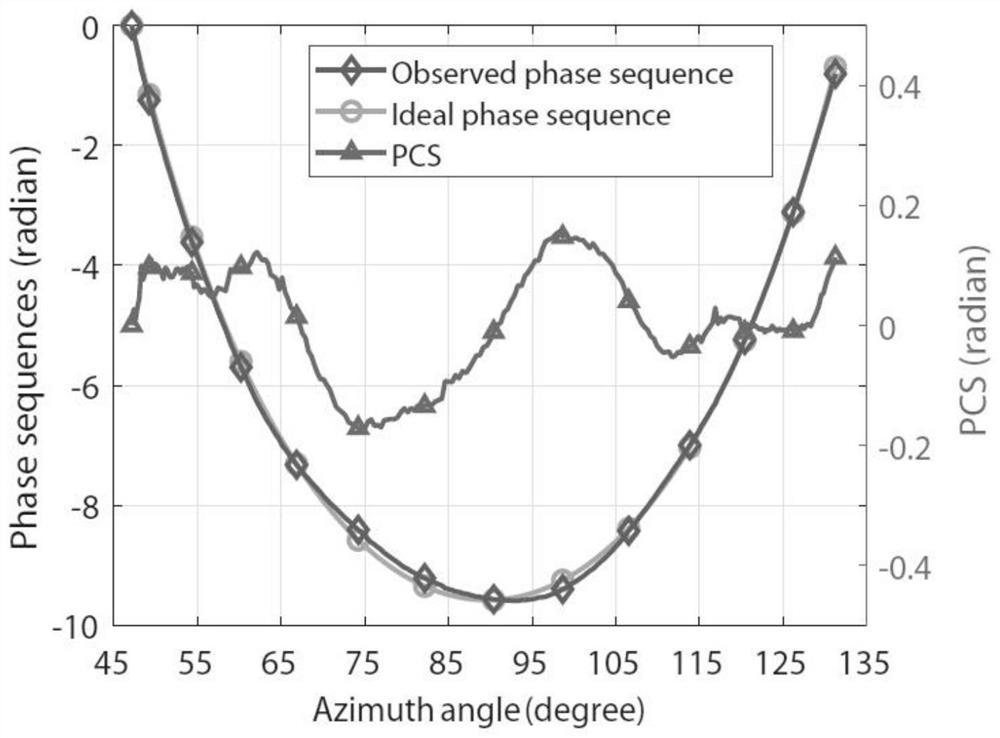
PCS will affect the observed phase and cause positioning errors

Method used


Image

  • A Positioning Method Based on RFID and Phase Calibration
  • A Positioning Method Based on RFID and Phase Calibration
  • A Positioning Method Based on RFID and Phase Calibration

Examples


Embodiment Construction

[0038] A positioning method based on RFID and phase calibration of the present invention will be further described below in conjunction with the accompanying drawings.

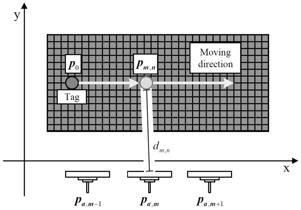
[0039] Tag positioning scenarios based on synthetic aperture technology such as figure 1 shown. In the tag data collection stage, a 4m×4m scene to be positioned is established. The moving track of the reader antenna is a straight line along the X axis, which is located at the boundary of the area to be positioned 20cm, and the total length is 4m. The tag is collected every 4cm space interval. Therefore, the operating frequency of the reader is 867.5MHz, the corresponding wavelength is 34.6cm, and the antenna collects 100 (N=100) readings during the movement. In the pixel database building stage, the pixel point spacing in the area to be positioned can be set to 5cm. If you want to obtain higher positioning accuracy, you can set the pixel points more densely.

[0040] The positioning method of the present inv...


PUM


Abstract

The invention discloses a positioning method based on RFID and phase calibration, which includes a tag data collection stage, a pixel database establishment stage, and a matching and positioning stage, wherein the matching and positioning stage includes the following steps: establishing a phase center offset library; Calibration technology is added to the positioning process to establish a matching function, and the positioning problem is transformed into finding the grid point that maximizes

Description

technical field [0001] The invention belongs to the technical field of RFID positioning, and aims at the problem of locating tags by utilizing tag phase obtained by a reader antenna moving along a known track and phase calibration technology. Background technique [0002] With the popularization of mobile Internet and smart phones, location-based services (Location Based Service, LBS) have received extensive attention, driving the development of various modern navigation and positioning technologies. The well-known outdoor positioning technology GPS cannot be applied to indoor positioning due to the occlusion of buildings and other reasons. In recent years, many indoor positioning technologies based on wireless networks have emerged, such as WiFi positioning, Bluetooth positioning, ZigBee positioning and RFID positioning. The rapid development of Internet of Things technology has made RFID technology widely used in the positioning, tracking and backtracking of production, l...

Claims


Application Information

Patent Timeline
Patent Type & Authority Patents(China)
IPC IPC(8): G01S5/02G06K7/10
CPCG01S5/0252G06K7/10099
Inventor 马永涛刘涵凯
Owner TIANJIN UNIV
Learn More