
Underwater sound communication system

A technology of underwater acoustic communication and sonar, which is applied in transmission systems, multi-frequency code systems, baseband system components, etc., can solve the problems of frequency selective deep fading, code element rate should not be too large, etc., and achieve peak-to-average power ratio Low, strong anti-multipath interference ability, and the effect of meeting the system performance requirements

Inactive Publication Date: 2012-05-09
SOUTH CHINA UNIV OF TECH
View PDF3 Cites 0 Cited by
  • Summary
  • Abstract
  • Description
  • Claims
  • Application Information

AI Technical Summary

Problems solved by technology

[0008] (2) SC-FDE is not as sensitive to carrier frequency offset as OFDM;
[0020] MIMO technology can utilize multipath components in propagation, that is, resist multipath fading, and can increase channel capacity and increase information transmission rate without increasing bandwidth. However, MIMO technology is still helpless for frequency selective deep fading
SC-FDE technology can suppress the frequency selective fading of signals and improve spectrum utilization. Spread spectrum technology can resist interference and multipath, and can realize reliable communication under low signal-to-noise ratio. It has good confidentiality, but underwater multipath Therefore, it is necessary to combine MIMO technology, spread spectrum technology and SC-FDE technology, which can not only suppress the multipath of the underwater acoustic channel Interference can also overcome the frequency selective deep fading of the signal, increase the channel capacity, and improve the information transmission rate

Method used


Image

  • Underwater sound communication system
  • Underwater sound communication system
  • Underwater sound communication system

Examples


Embodiment Construction

[0038] The present invention will be described in detail below in conjunction with the accompanying drawings, but the embodiments of the present invention are not limited thereto.

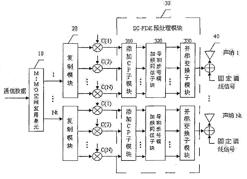
[0039] The transmitter circuit module of the present invention is as figure 1 As shown, it mainly consists of MIMO spatial multiplexing unit 10, Nt replication modules 20, N×Nt multipliers, Nt SC-FDE preprocessing modules 30, Nt adding CP submodules 310, Nt adding pilots and The synchronization signal sub-module 320, Nt parallel-to-serial conversion sub-modules 330, Nt transmitting sonars 40, etc. are composed.

[0040] The MIMO spatial multiplexing unit 10 divides the communication data S(t) to be transmitted into Nt branches and transmits them in parallel through hierarchical space-time coding, which becomes , respectively sent to the branches where the Nt spreading units are located.

[0041] For any one of the Nt spreading units, each spreading unit is composed of 1 replication module 20 and...


PUM


Abstract

The invention discloses an underwater sound communication system, wherein a transmitter comprises an MIMO space multiplexing unit, a plurality of spectrum spreading units, a plurality of SC-FDE pretreatment modules and a plurality of transmitting sonars; a plurality of output ends of the MIMO space multiplexing unit are in one-to-one connection with the plurality of the spectrum spreading units; each spectrum spreading unit is connected to one SC-FDE pretreatment module; each SC-FDE pretreatment module is connected to one transmitting sonar; a receiver comprises a plurality of receiving sonars, a plurality of filtering detecting units, a plurality of SC-FDE modules, a plurality of dispreading units, and an MIMO demultiplexing unit; each receiving sonar is connected with one filtering detecting unit; each filtering detecting unit is connected to one SC-FDE module; each SC-FDE module is connected to one dispreading unit; and the plurality of the dispreading units are in one-to-one connection with a plurality of input ends of the MIMO demultiplexing unit. The system can resist multipath interface, improve frequency spectrum utilization ratio, channel capacity, information transmission rate and confidentiality, compensate Doppler frequency shift and reduce signal-to-noise ratio.

Description

technical field [0001] The invention belongs to the technical field of underwater acoustic communication, and in particular relates to an underwater acoustic communication system. Background technique [0002] The natural environment where underwater acoustic communication technology is applied is generally shallow sea. In shallow seas, the main environmental noises include hydrodynamic noise (500Hz-50kHz), seawater thermal noise (50kHz-200kHz), etc. Most remote underwater acoustic channels can only transmit signals below 15kHz. Compared with radio communication and wired communication, underwater acoustic channel is a time-varying, space-varying, and frequency-varying random narrowband channel. Severe multi-path interference and Doppler frequency deviation are the main reasons for the high bit error rate of underwater acoustic communication. Reasons, multipath propagation effect, ocean current influence, energy propagation on the seabed and other factors cause signal time-...

Claims


Application Information

Patent Timeline
Patent Type & Authority Patents(China)
IPC IPC(8): H04L25/03H04L27/26H04B13/02
Inventor 韦岗崔玲张军
Owner SOUTH CHINA UNIV OF TECH
Learn More