Piezoelectric tunnel airflow generator

A generator, piezoelectric technology, applied in the direction of generator/motor, piezoelectric effect/electrostrictive or magnetostrictive motor, electrical components, etc., can solve the difficulty of subsequent maintenance of cables, limited battery life, Inconvenient use and other problems, to achieve the effects of high reliability, strong power generation capacity, and controllable deformation

Active Publication Date: 2020-03-24
ZHEJIANG NORMAL UNIVERSITY
View PDF8 Cites 1 Cited by
  • Summary
  • Abstract
  • Description
  • Claims
  • Application Information

AI Technical Summary

Problems solved by technology

If the traditional cable is used for power supply, the cable laying and subsequent maintenance are more difficult and costly; if the battery is used for power supply, due to the limited life of the battery, it needs to be replaced frequently, which is extremely inconvenient to use, especially in remote mountainous areas

Method used


Image

  • Piezoelectric tunnel airflow generator
  • Piezoelectric tunnel airflow generator
  • Piezoelectric tunnel airflow generator

Examples


Embodiment Construction

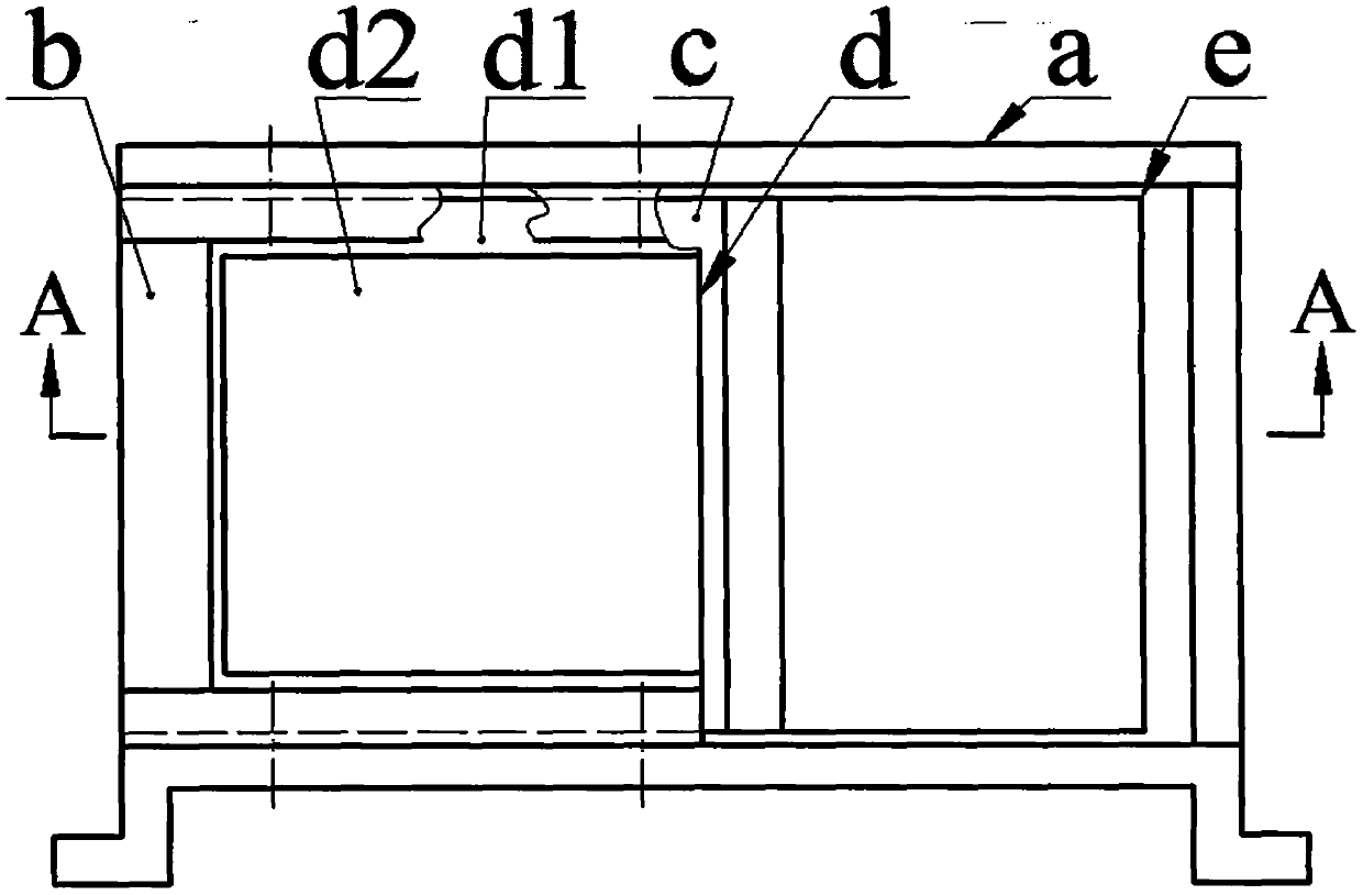
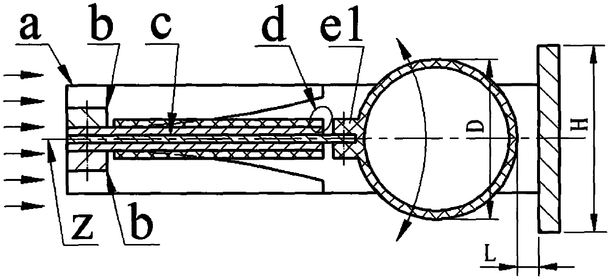
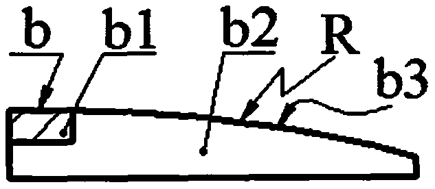
[0014] The bracket a is composed of the upper beam a1, the lower beam a2 and the baffle a3 connecting the upper beam a1 and the lower beam a2, the two ends of the lower beam a2 are provided with the feet a4, the upper beam a1 and the lower beam a2 are located on the same side of the baffle a3 and Symmetrical configuration; the shape-limiting frame b is composed of the beam b1 and the shape-limiting block b2 at both ends of the beam b1, the shape-limiting block b2 is provided with a shape-limiting surface b3, and the shape-limiting surface b3 is an arc surface; the beam b1 of the two shape-limiting frames b Connected by screws and the shape-limiting surface b3 is oppositely installed, two piezoelectric vibrators d and an elastic piece c are crimped between the two beams b1, the piezoelectric vibrator d is located on both sides of the elastic piece c; the piezoelectric vibrator d is formed by the substrate d1 is composed of a piezoelectric sheet d2 bonded to one side; the distanc...


PUM


Abstract

The invention relates to a piezoelectric tunnel airflow generator, and belongs to the technical field of new energy. A support is composed of an upper beam, a lower beam, and a baffle connecting the upper beam and the lower beam. The upper beam and the lower beam are located on the same side of the baffle and are symmetrically arranged. Each shape limiting frame is composed of a beam and shape limiting blocks at the two ends of the beam, and arc shape limiting faces are arranged on the shape limiting blocks. The cross beams of the two shape limiting frames are connected through screws, the shape limiting surfaces are oppositely installed, two piezoelectric vibrators and an elastic sheet are connected between the two cross beams in a pressing mode, and the piezoelectric vibrators are located on the two sides of the elastic sheet; each piezoelectric vibrator is composed of a substrate and a piezoelectric plate bonded to one side of the substrate. One side of the substrate is in contact with the elastic sheet, the root of the other side of the substrate is in contact with the shape-limiting surface, and the piezoelectric sheet is not in contact with the shape-limiting surface; the shape limiting blocks at the two ends of the shape limiting frames are connected with the upper beam and the lower beam respectively, and the lug plate of bluff body is installed at the free end of the elastic piece and close to the baffle; and the symmetric center layer in the thickness direction of the elastic sheet, the center line of the bluff body and the symmetric center layer in the width direction of the baffle are positioned in the same vertical plane when not in work.

Description

technical field [0001] The invention belongs to the technical field of new energy, and in particular relates to a piezoelectric tunnel airflow generator. Background technique [0002] Tunnels have become an important part of the current road and rail network. In order to ensure that cars and trains can travel together normally and safely, and realize real-time monitoring of the tunnel environment and passing vehicles, various instruments and lighting facilities need to be installed in the tunnel, so there must also be corresponding power supply facilities in the tunnel. If the traditional cable is used for power supply, the cable laying and subsequent maintenance are more difficult and costly; if the battery is used for power supply, due to the limited life of the battery, it needs to be replaced frequently, which is extremely inconvenient to use, especially in remote mountainous areas. Contents of the invention [0003] The present invention proposes a piezoelectric tunn...

Claims


Application Information

Patent Timeline
Patent Type & Authority Applications(China)
IPC IPC(8): H02N2/18
CPCH02N2/185
Inventor 蒋永华廖卫林王淑云黄芳胜杜洁雅武佳萌曾平
Owner ZHEJIANG NORMAL UNIVERSITY
Why Eureka
Try Eureka