A Piezoelectric Energy Harvester Used in River Monitoring System

A monitoring system, piezoelectric energy harvesting technology, applied in piezoelectric effect/electrostrictive or magnetostrictive motors, electrical components, generators/motors, etc. Dike overflow and other problems, to achieve the effect of uniform stress distribution, fast response speed, and strong power generation capacity

Active Publication Date: 2021-11-12
ZHEJIANG NORMAL UNIVERSITY
View PDF7 Cites 0 Cited by
  • Summary
  • Abstract
  • Description
  • Claims
  • Application Information

AI Technical Summary

Problems solved by technology

In recent years, due to insufficient treatment of industrial wastewater, soil erosion, and improper use of pesticides and fertilizers, some rivers have been polluted to a certain extent, unable to meet the needs of residents' lives and farmland irrigation.
In addition, due to the imperfect flood control facilities and lack of relevant flood control facilities for small and medium-sized rivers in some areas, there are dangers of embankment collapse or flooding when the flood season approaches, which directly threatens the lives and property safety of people along the coast.
Therefore, river monitoring has been highly valued by relevant state departments; at the same time, domestic experts and scholars have also proposed corresponding monitoring methods and means, including water quality monitoring technology for river water pollution, rainfall, water level and other natural disasters for flood control and mudslides. There are many monitoring technologies such as river water flow rate, as well as various micro energy harvesters that supply power to the monitoring system. However, the existing micro energy harvesters have certain problems in terms of reliability and flow rate adaptability, which seriously hampered its promotion

Method used


Image

  • A Piezoelectric Energy Harvester Used in River Monitoring System
  • A Piezoelectric Energy Harvester Used in River Monitoring System
  • A Piezoelectric Energy Harvester Used in River Monitoring System

Examples


Embodiment Construction

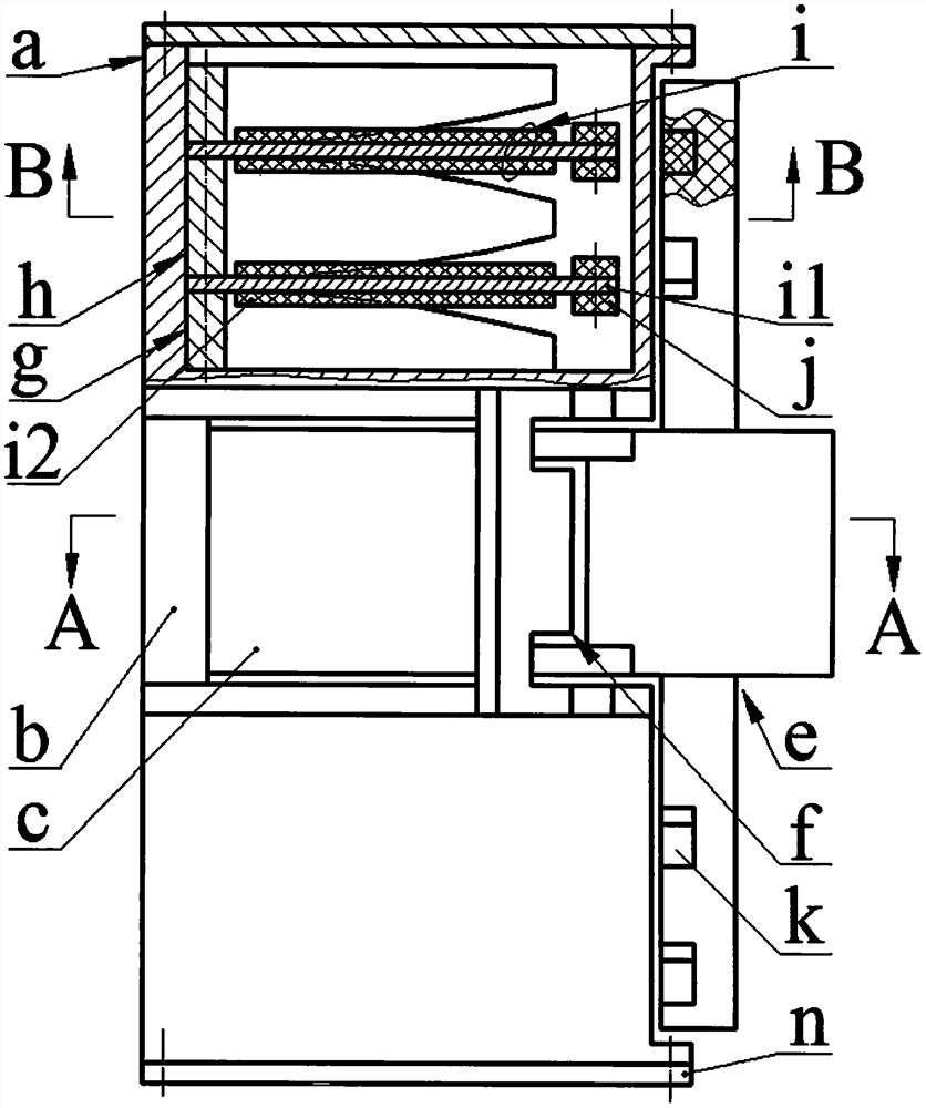
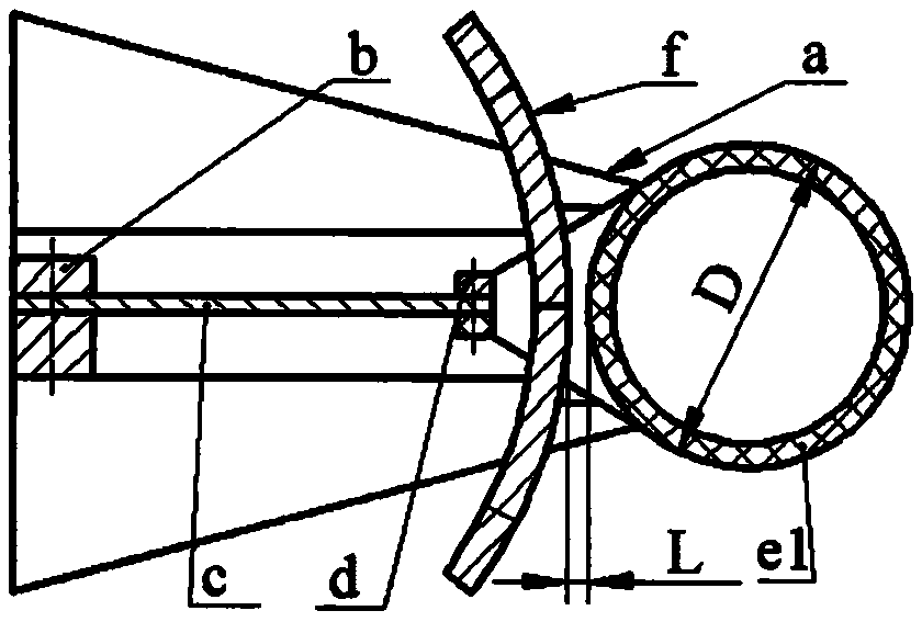
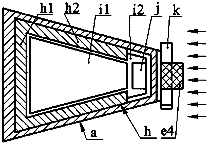
[0019] Both ends of the main beam a1 of the frame a are provided with sub-beam a2, and the sub-beam a2 is perpendicular to the main beam a1 and symmetrically arranged at both ends of the main beam a1, and the outer side of the sub-beam a2 is provided with a cavity a3, and the cavity a3 The end of the side wall is installed with an end cover n through screws; the side beams g1 of two side frames g and the middle beam h1 of at least one middle frame h are installed on the side wall close to the sub-beam a2 in the cavity a3 through screws, and the piezoelectric One end of the vibrator i is crimped between the side beam g1 and the middle beam h1 to form a cantilever beam structure. The piezoelectric vibrator i is composed of the substrate i1 and the piezoelectric sheet i2 bonded to both sides. The materials of the substrate i1 and the piezoelectric sheet i2 Brass and PZT4 respectively, the free end of the piezoelectric vibrator i is installed with a secondary magnet j through screw...


PUM


Abstract

The invention relates to a piezoelectric energy harvester used in a river monitoring system, belonging to the technical field of new energy. There are sub-beams at both ends of the main beam of the frame, and a cavity is provided on the outside of the sub-beam; the side beams of the side frame and the middle beam of the middle frame are installed on the side wall of the cavity close to the sub-beam, and are bonded by the base plate and the piezoelectric sheet. One end of the piezoelectric vibrator is crimped between the side beam and the middle beam, and the other end is equipped with a secondary magnet; one side of the side ear plates at both ends of the side beam and both sides of the middle ear plate at both ends of the middle beam are equipped with a shape-limiting On the surface, the distance between the side ear plates is equal to the distance between the middle ear plates and is wider than the piezoelectric sheet and narrower than the base plate; the side ears at both ends of the blunt body of the coupler are connected by a horizontal plate, and the horizontal plate is equipped with a leaf spring, and the other end of the leaf spring is fixed on the main beam Above; the outer sides of both ends of the blunt body are equipped with side arms embedded with main magnets, and the main magnets are symmetrically installed on the two side arms to form the same angle with the axis of the blunt body, and the main and auxiliary magnets attract each other; two baffles are installed on the sub-beam and its curved plates lean against each other, and the convex surface of the curved plates is close to the blunt body.

Description

technical field [0001] The invention belongs to the technical field of new energy, and in particular relates to a piezoelectric energy harvester used in a river monitoring system, which is used to construct a self-powered river monitoring system. Background technique [0002] There are thousands of rivers all over the territory of our country. In recent years, due to inadequate treatment of industrial wastewater, soil erosion, and improper use of pesticides and fertilizers, some rivers have been polluted to a certain extent, unable to meet the needs of residents and farmland irrigation. In addition, due to the imperfect flood control facilities and lack of relevant flood control facilities for small and medium-sized rivers in some areas, there are dangers of embankment collapse or flooding when the flood season approaches, which directly threatens the lives and property safety of people along the coast. Therefore, river monitoring has been highly valued by relevant state de...

Claims


Application Information

Patent Timeline
Patent Type & Authority Patents(China)
IPC IPC(8): H02N2/18
CPCH02N2/185H02N2/186
Inventor 王淑云柴超辉罗素清施继忠张可任泽峰吴鸣
Owner ZHEJIANG NORMAL UNIVERSITY
Why Eureka
Try Eureka