
A vortex-induced vibration piezoelectric generator

A vortex-induced vibration and generator technology, which is applied in the direction of generator/motor, piezoelectric effect/electrostrictive or magnetostrictive motor, engine components, etc. Problems such as dikes and other problems are achieved, and the effects of high reliability, strong power generation capacity and high resonance frequency are achieved.

Active Publication Date: 2021-10-08
合肥九州龙腾科技成果转化有限公司
View PDF7 Cites 0 Cited by
  • Summary
  • Abstract
  • Description
  • Claims
  • Application Information

AI Technical Summary

Problems solved by technology

In recent years, due to insufficient treatment of industrial wastewater, soil erosion, and improper use of pesticides and fertilizers, some rivers have been polluted to a certain extent, unable to meet the needs of residents' lives and farmland irrigation.
In addition, due to the imperfect flood control facilities and lack of relevant flood control facilities for small and medium-sized rivers in some areas, there are dangers of embankment collapse or flooding when the flood season approaches, which directly threatens the lives and property safety of people along the coast.
Therefore, river monitoring has been highly valued by relevant state departments; at the same time, domestic experts and scholars have also proposed corresponding monitoring methods and means, including water quality monitoring technology for river water pollution, rainfall, water level and other natural disasters for flood control and mudslides. There are many monitoring technologies such as river water flow rate, as well as various micro energy harvesters that supply power to the monitoring system. However, the existing micro energy harvesters have certain problems in terms of reliability and flow rate adaptability, which seriously hampered its promotion

Method used


Image

  • A vortex-induced vibration piezoelectric generator
  • A vortex-induced vibration piezoelectric generator
  • A vortex-induced vibration piezoelectric generator

Examples


Embodiment Construction

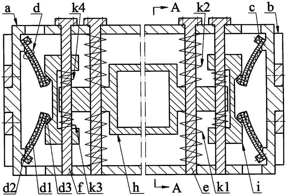
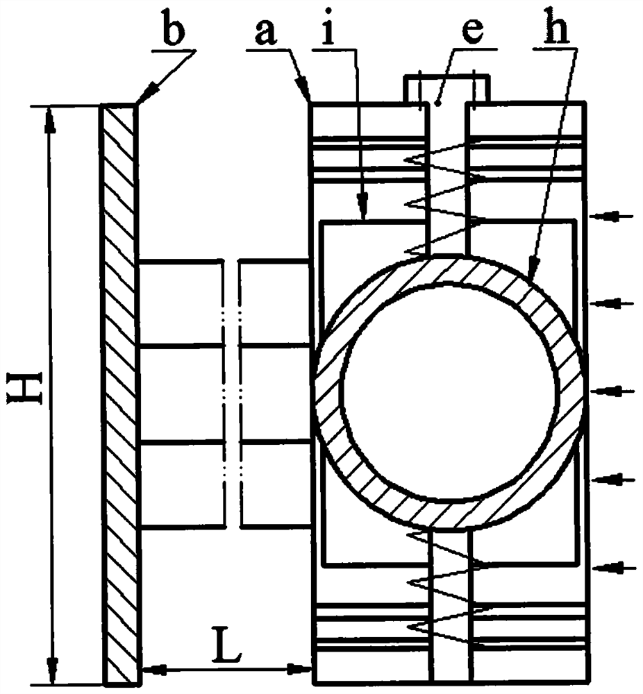
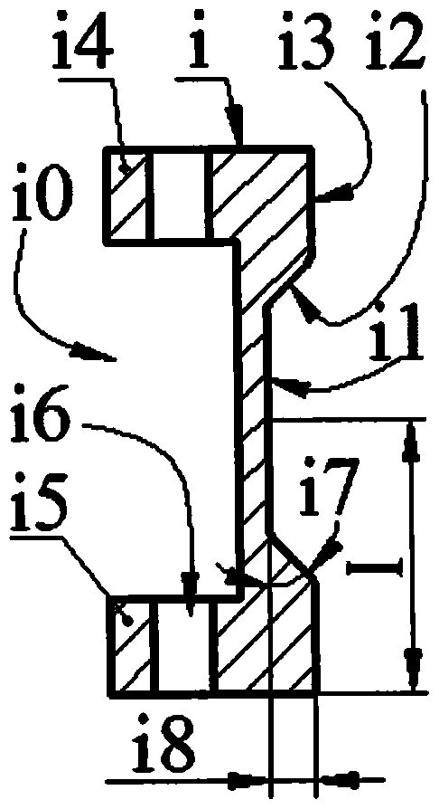
[0015] The inner side of the longitudinal wall a1 on the left and right sides of the frame a is symmetrically provided with a protrusion a3 with an inclined installation surface a0, and a guide plate a4 is arranged on the outer side, and the acute angle formed between the installation surface a0 and the longitudinal wall a1 is greater than 30 degrees; the frame a Two sets of main pin holes a7, auxiliary pin holes a6 and process holes a5 are symmetrically arranged on the upper and lower sides of the horizontal wall a2; the left and right sides of the baffle b are equipped with outer ear plates b1 with chute b2, the outer ear plates The chute b2 of b1 is set on the guide plate a4 of the frame a, and the outer ear plate b1 is fixed on the longitudinal wall a1 by screws; there is a cam I on one side of the exciter i, and the cam I is a moving cam, and the cam surfaces of the cam I are connected in sequence The bottom surface i1, the slope i2 and the top surface i3 are formed, the d...


PUM


Abstract

The invention relates to a vortex-induced vibration piezoelectric generator, which belongs to the field of new energy. The inner sides of the longitudinal walls on the left and right sides of the frame are provided with inclined installation surfaces, and the outer ear plates on the left and right sides of the baffle are fixed on the longitudinal walls of the frame; one side of the exciter is provided with a cam composed of a bottom surface, an inclined surface and a top surface, and the other side is provided with a cam. There is a through groove, and guide holes are set on the upper and lower walls of the through groove; the left and right ends of the blunt body of the coupler are provided with inner ear plates with main and auxiliary guide holes, and the main hole and the auxiliary guide hole are respectively sleeved on the main pin and the auxiliary pin. The upper and lower ends of the main and auxiliary pins are respectively fixed on the transverse wall of the frame; the inner ear plate of the coupler press-connects the supporting spring and the buffer spring to the transverse walls on the upper and lower sides of the frame respectively; the exciter is installed on the auxiliary pin through the guide hole. The upper and lower springs are crimped between the upper and lower walls of the groove and the inner ear plate; the piezoelectric vibrator of the cantilever beam with the top block at the free end is fixed on the mounting surface of the frame; The amount of pre-bending deformation generated by the vibrator installation is half of its allowable value.

Description

technical field [0001] The invention belongs to the technical field of new energy, and in particular relates to a vortex-induced vibration piezoelectric generator, which is used to construct a self-powered river monitoring system. Background technique [0002] There are thousands of rivers all over the territory of our country. In recent years, due to inadequate treatment of industrial wastewater, soil erosion, and improper use of pesticides and fertilizers, some rivers have been polluted to a certain extent, unable to meet the needs of residents and farmland irrigation. In addition, due to the imperfect flood control facilities and lack of relevant flood control facilities for small and medium-sized rivers in some areas, there are dangers of embankment collapse or flooding when the flood season approaches, which directly threatens the lives and property safety of people along the coast. Therefore, river monitoring has been highly valued by relevant state departments; at th...

Claims


Application Information

Patent Timeline
Patent Type & Authority Patents(China)
IPC IPC(8): H02N2/18F03B13/00
CPCF03B13/00H02N2/185H02N2/188
Inventor 王淑云杨泽盟万嫩刘立博任泽峰毛燕飞施继忠曾平
Owner 合肥九州龙腾科技成果转化有限公司
Learn More