A micromass sensor based on a trough-shaped cantilever beam structure

A cantilever beam and micro-mass technology, applied in the field of sensors, can solve problems such as high cost, complex optical displacement measurement system, and difficult measurement

Inactive Publication Date: 2011-12-07
DALIAN UNIV OF TECH
View PDF16 Cites 24 Cited by
  • Summary
  • Abstract
  • Description
  • Claims
  • Application Information

AI Technical Summary

Problems solved by technology

However, since this technology needs to be carried out in a vacuum environment, and the calculation model is complex, and the adsorption position of the measured atoms will directly affect the measurement results, the entire measurement project is complicated, poorly controllable, and expensive, so it is not suitable for biochemical detection.
US patent US 6389877B1 and domestic patent CN1250156A use single-head and double-head cantilever structures to measure frequency. Although the adsorption area is increased by increasing the cantilever area, the system effective mass M of the cantilever beam is also increased. e , which is not conducive to the improvement of sensor sensitivity
Recently, the domestic invention patent publication number CN 1609555A proposes to measure the quality by measuring the displacement difference of the vibrator with the probe adsorbed on it, but a complex optical displacement measurement system is required, which increases the measurement cost
[0005] A comprehensive analysis found that although reducing the size of the sensor can improve its minimum mass measurement accuracy and sensitivity, the resulting measurement difficulties, reduced range and harsh measurement environment requirements have seriously affected its scope of application.

Method used


Image

  • A micromass sensor based on a trough-shaped cantilever beam structure
  • A micromass sensor based on a trough-shaped cantilever beam structure
  • A micromass sensor based on a trough-shaped cantilever beam structure

Examples


Embodiment 1

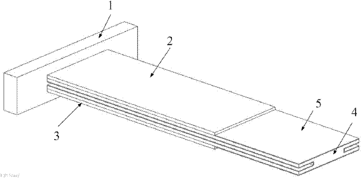
[0038] figure 1 A structural schematic diagram of a piezoelectric micromass sensor based on a slot-shaped beam structure is given. Among them, the upper piezoelectric film 2 and the lower piezoelectric film 3 are respectively connected to the upper and lower surfaces of the channel-shaped cross-section beam 4 to form a cross-sectional symmetrical structure, and one end thereof is connected to the fixed block 1 to form a cantilever beam structure. The part including the inner surface of the groove is covered with the detector adsorption film 5 . Among them, the trough section beam 4 is made of highly elastic material, and the polarization modes of the upper piezoelectric film 2 and the lower piezoelectric film 3 are the same, and they are connected into the frequency measurement circuit system in parallel or in series, and the cantilever caused by the adsorption of the probe is measured. The beam resonance frequency change value is calculated to obtain the mass of the object t...

Embodiment 2

[0044] Figure 4 A schematic structural diagram of a piezoelectric micromass sensor based on a cantilever beam with a slot section is shown. On the basis of Embodiment 1, the lower piezoelectric film 3 is removed to form a mass sensor device consisting of an upper piezoelectric film 2 , a slot-shaped cantilever beam 4 , a fixed block 1 and a probe adsorption film 5 . During the detection process, the lower piezoelectric film 3 is connected to the frequency test system to obtain the frequency variation caused by the probe, and then obtain the micromass adsorbed by the probe adsorption film 5 . Among them, the cantilever beam part of the sensor is a double-layer combined structure of different materials, and its resonance frequency satisfies the following formula:

[0045] f 1 i = λ 1 i 2 ...

Embodiment 3

[0049] Figure 5 A structural schematic diagram of a piezoelectric micromass sensor based on a slot-shaped cross-section cantilever beam is shown. On the basis of Embodiment 1, the I-shaped cross-section channel beam 4 is replaced by a back-shaped channel-shaped beam 6. At this time, the detection object adsorption film 5 covers the outer surface and inner surface of the extension part of the cantilever beam 6, The substance to be detected is adsorbed on the outer surface and inner surface of the back-shaped groove-shaped cross-section beam 6, and the frequency measurement circuit system tests the frequency difference of the cantilever beam before and after the adsorption. In addition, in this embodiment, the measurement of microscopic mass can also be realized by using a single piezoelectric film, such as Image 6 As shown, the corresponding structure frequency change formula is calculated and measured according to the method in the second embodiment.


PUM


Abstract

The invention discloses a micro mass sensor based on a groove-shaped cantilever beam structure, and belongs to the technical field of sensors. In the groove-shaped cantilever beam of the sensor, one end of a fixed bock is provided with 1-2 same piezoelectric films, and a test substance adsorption film covers a cantilever end; and a resonant frequency difference delta f before and after the cantilever structure adsorbs a test substance is measured, and the mass m of the test substance is calculated further. By the introduction of the groove-shaped cantilever beam, the natural frequency of vibration and the adsorption area are increased, the sensitivity of the sensor is improved, and the measuring stability of the sensor is improved. The frequency change of the sensor caused by the mass of the adsorption film can be accurately measured through the piezoelectric films, and the mass of the test substance is calculated. The sensor has the characteristics of simple structure, large adsorption area, wide mass measuring range, high stability and sensitivity and the like, and the sensitivity can be improved by 20 percent to the maximum compared with that of a rectangular-section mass sensor with the same size particularly, so the sensor can be widely applied to measuring concentrations of gases/liquids, microparticles, dust, microbes such as bacteria or viruses and the like.

Description

technical field [0001] The invention relates to a micromass sensor based on a trough-shaped cantilever beam structure and a realization method thereof, belonging to the technical field of sensors, and mainly used for high-precision measurement of liquid concentration, air dust, and microorganisms such as bacteria or virus mass. Background technique [0002] The piezoelectric micromass sensor mainly detects the material composition by measuring the structural resonance frequency change caused by the mass of the material attached to the sensor surface. It has the characteristics of simple structure, fast response, low cost and high precision. It overcomes the ultra-high frequency bulk acoustic wave The detection method, enzyme-linked analysis method, fluorescent labeling method, etc. have the problems of expensive detection equipment, time-consuming and cumbersome signal acquisition process, and have a wide range of applications in microbial detection such as bacteria and virus...

Claims


Application Information

Patent Timeline
Patent Type & Authority Applications(China)
IPC IPC(8): G01G3/16
Inventor 高仁璟赵剑刘书田黄毓
Owner DALIAN UNIV OF TECH
Why Eureka
Try Eureka