Self dampening rotary shaft

Inactive Publication Date: 2005-09-29
GKN DRIVELINE NORTH AMERICA
View PDF8 Cites 20 Cited by
  • Summary
  • Abstract
  • Description
  • Claims
  • Application Information

AI Technical Summary

Benefits of technology

[0008] It is a principle object of the present invention to provide an improved driveshaft operative

Problems solved by technology

As those skilled in the art are aware, at certain rotational speeds and resonant frequencies, the above referenced propshafts and driveshafts (hereinafter collectively referred to as driveshafts), are known to exhibit unbalanced rotation and thus undesirable vibrations.
These vibrations, in turn, are known to result in bending or torsional forces within and along the length of the respective driveshaft.
It is obvious that such bending or t

Method used


Image

  • Self dampening rotary shaft
  • Self dampening rotary shaft
  • Self dampening rotary shaft

Examples


Embodiment Construction

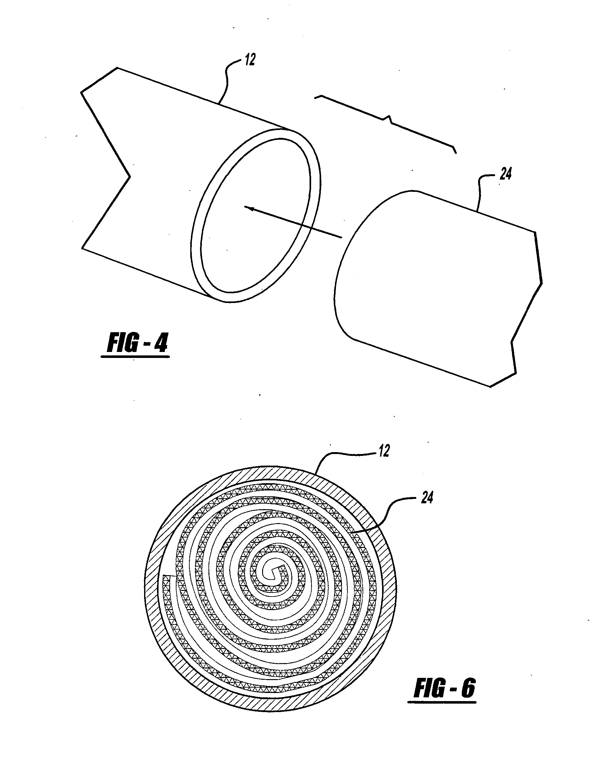
[0023] Referring first to FIG. 5 there is shown generally by reference numeral 10, a representative driveshaft assembly of a motor vehicle. Assembly 10 comprises a front propeller shaft (“propshaft”) 12 shown operatively connected to a constant velocity joint such as but not limited to a “VL” style plunging constant velocity joint 14. As those skilled in the art are aware, constant velocity joints are employed where transmission of a constant velocity rotary motion is desired or required. Plunging tripod joints in particular are currently used inboard (transmission side) in front wheel drive vehicles, and particularly in the propeller shafts found in rear wheel drive, all-wheel drive and 4-wheel drive vehicles. Plunging tripod universal joints allow the interconnection of shafts to change length during operation without the use of splines. The “VL” style plunging constant velocity joint 14 is therefore characterized by the performance of end motion in the joint with a minimum of fri...


PUM

PropertyMeasurementUnit
Fractionaaaaaaaaaa
Lengthaaaaaaaaaa
Electrical resistanceaaaaaaaaaa

Abstract

A rotary shaft includes internal self-dampening means for absorbing rotational energy generated by the rear axle and/or clutch of a motor vehicle.

Description

TECHNICAL FIELD [0001] The present invention relates to a liner for use with a rotary driveshaft. More particularly, this invention relates to a liner which is affixable to a rotary driveshaft for use on a conventional automotive vehicle to increase the resonance frequency of bending of the driveshaft and reduce undesirable vibrations. BACKGROUND ART [0002] There are generally four (4) main types of automotive power train (“driveline systems”). More specifically, there exists a full-time front wheel drive system, a full-time rear wheel drive system, a part-time four wheel drive system, and an all-wheel drive system. Most commonly, the systems are distinguished by the delivery of power to different combinations of drive wheels, i.e., front drive wheels, rear drive wheels or some combination thereof. In addition to delivering power to a particular combination of drive wheels, most drive systems permit the respectively driven wheels to rotate at different speeds. For example, the outsi...

Claims


Application Information

Patent Timeline
IPC IPC(8): F16C3/00F16C3/02F16F15/10
CPCF16F15/10Y10T464/50F16C3/023F16C2326/06Y10T442/129Y10T442/119
Inventor CAMPBELL, CRAIG ANDREW
Owner GKN DRIVELINE NORTH AMERICA
Why Eureka
Try Eureka